Ejection device and inkjet head with silicon nozzle plate

a technology of inkjet head and nozzle plate, which is applied in the direction of magnetic recording, data recording, instruments, etc., can solve the problems of complex manufacturing process, time-consuming manufacture, and inability to reduce the cross-sectional area of the nozzle on the rear side, so as to prevent the deterioration of the accuracy of the groove in the depth direction caused by the etching applied to the wafer surface, and reduce the processing accuracy. the effect of speed

Inactive Publication Date: 2005-03-08
SEIKO EPSON CORP
View PDF26 Cites 21 Cited by
  • Summary
  • Abstract
  • Description
  • Claims
  • Application Information

AI Technical Summary

Benefits of technology

With this procedure, the through-hole can be formed simultaneously with the nozzle without lowering processing accuracy. When the through-hole is relatively large, it is preferable to form the second groove by etching into a shape which follows the contour of the outer periphery of the through-hole. Since the etching area of the portion of the through-hole can be reduced thereby, the reduction of etching speed can be prevented, and the deterioration of the accuracy of the grooves in a depth direction caused by the etching applied to a wafer surface can be prevented.

Problems solved by technology

That is, it is impossible to decrease the cross-sectional area of the nozzle on the rear side thereof.
Thus, all the sub-processes relating to the etching process, such as patterning including the formation of a resist film, masking, and the removal of the resist film, rinsing, and the like, must be carried out twice, whereby problems arise in that the manufacturing process is complex and the manufacture is time-consuming.

Method used


Image

  • Ejection device and inkjet head with silicon nozzle plate
  • Ejection device and inkjet head with silicon nozzle plate
  • Ejection device and inkjet head with silicon nozzle plate

Examples


Embodiment Construction

Example of an Inkjet Head to Which the Present Invention is Applied

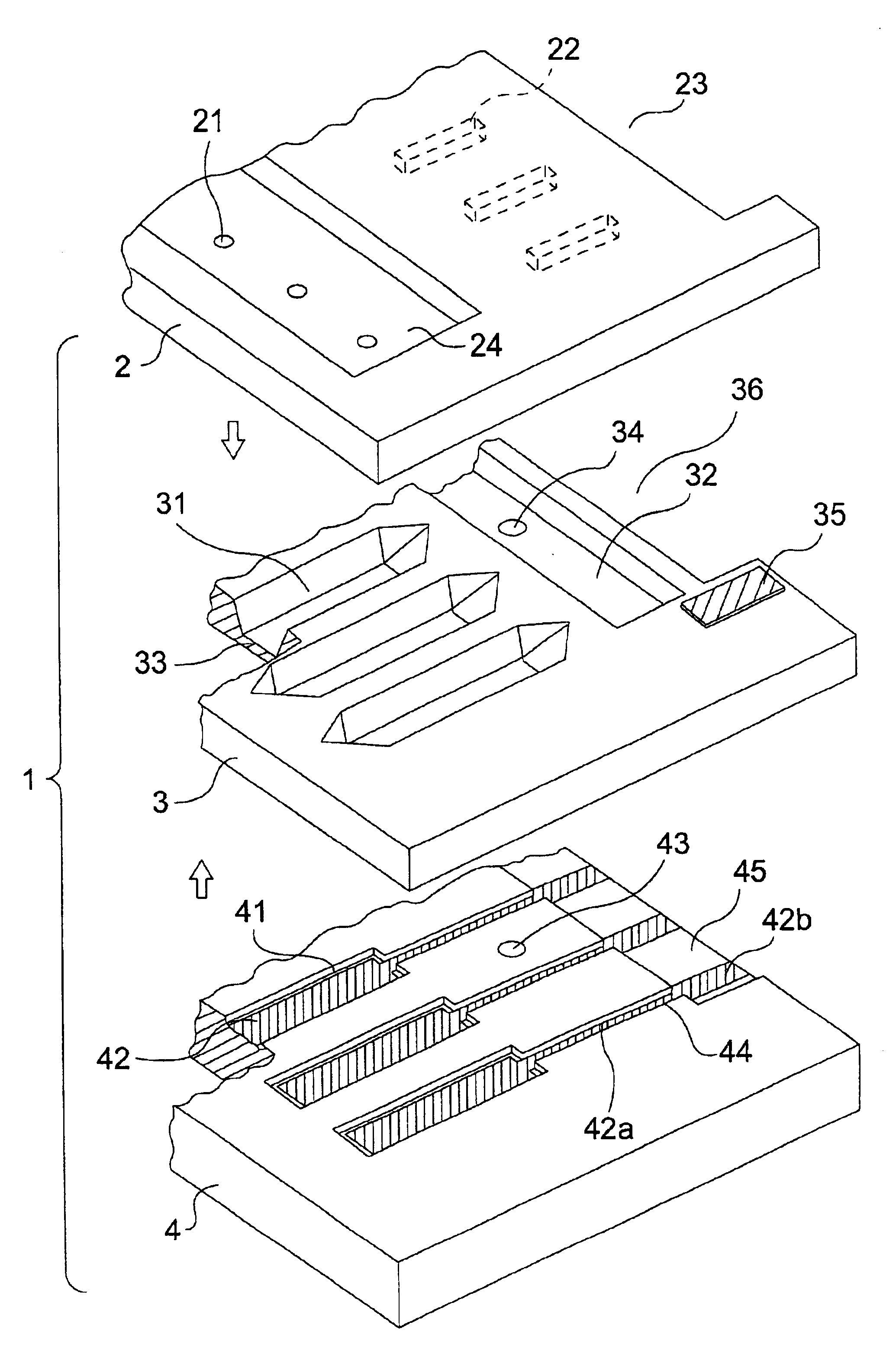
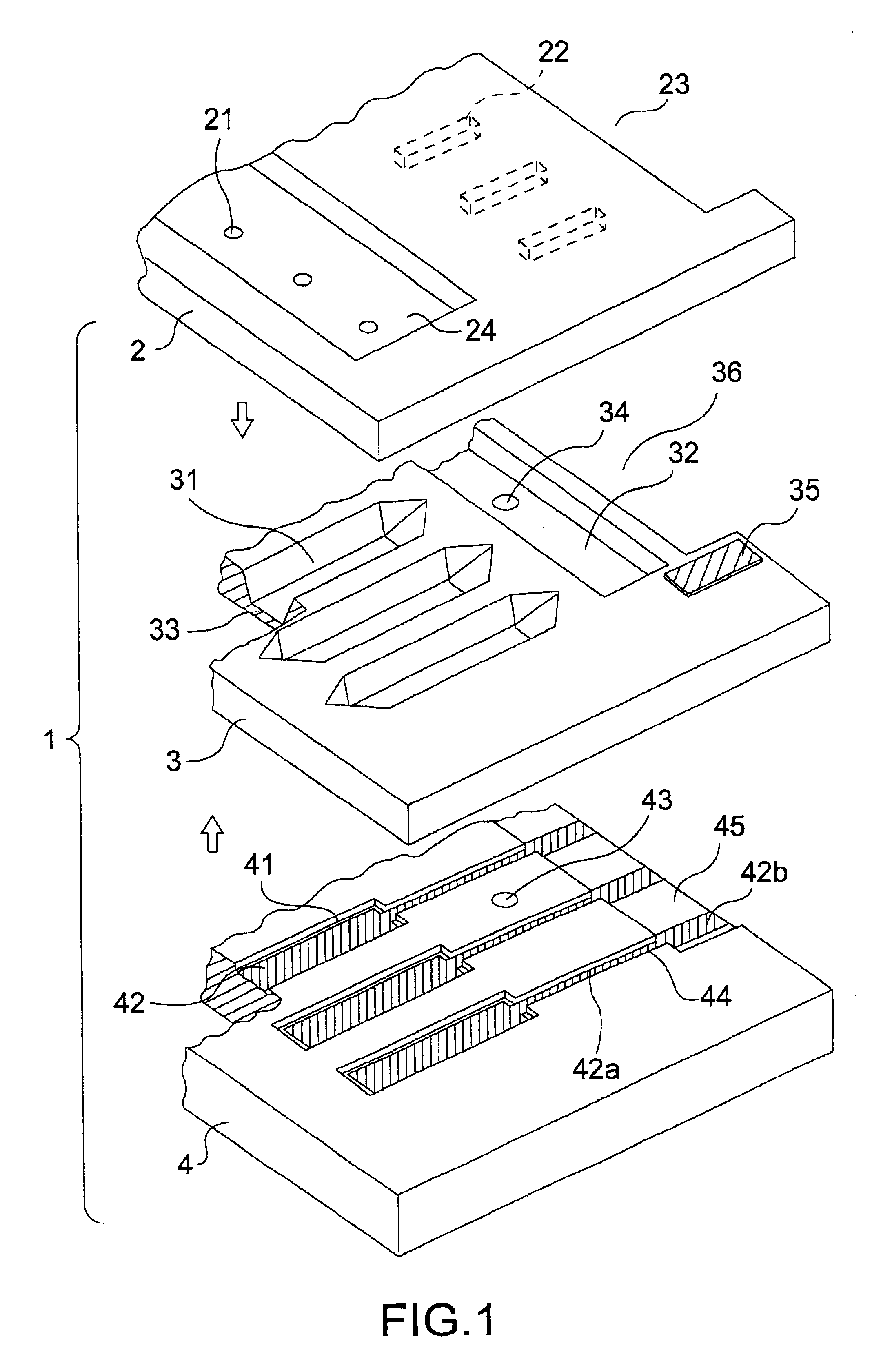
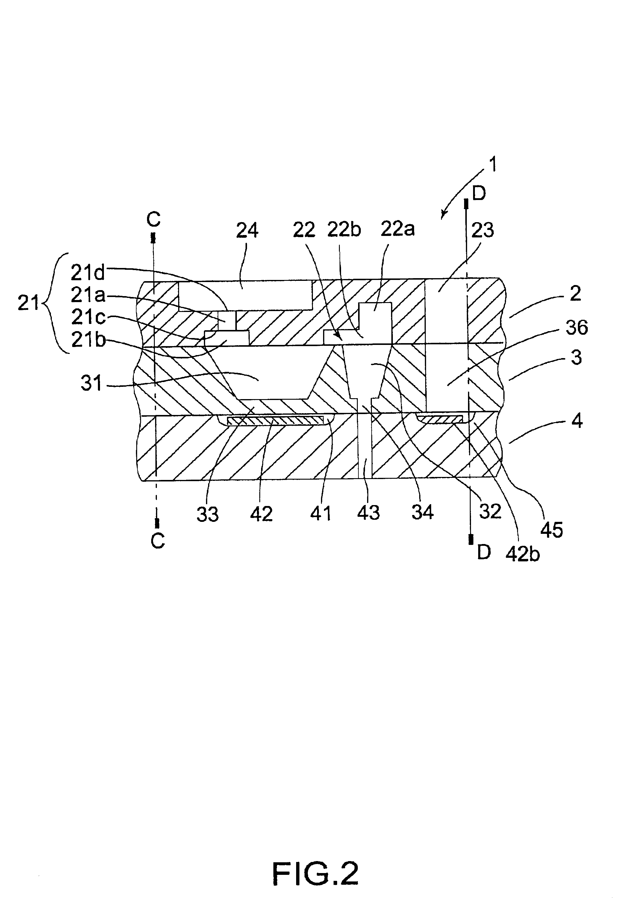
FIG. 1 is an exploded perspective view of an inkjet head to which a method of the present invention can be applied, and FIG. 2 shows a schematic cross-section of the inkjet head in FIG. 1.

Description below is made with reference to FIGS. 1 and 2; the inkjet head 1 of the example is an electrostatic drive type inkjet head similar to the inkjet head disclosed in Japanese Unexamined Patent Publication No. 5-50601, filed by the applicant. The inkjet head 1 is arranged by similarly bonding together a nozzle plate 2 (upper substrate) composed of a silicon monocrystalline substrate, a cavity plate 3 (first lower substrate) composed of a silicon monocrystalline substrate, and a glass substrate 4 (second lower substrate).

Note that while both figures show a single head to simplify description, patterns for a plurality of inkjet heads are formed on each of the substrates 2, 3, and 4. After the substrates are bonded together, th...


PUM


Abstract

A silicon nozzle plate includes nozzles each with a first nozzle portion having a circular cross-section and a second nozzle portion having a circular cross-section wherein the circular cross-section of the first nozzle portion is smaller than the circular cross-section of the second nozzle portion. In one embodiment the nozzle plate is utilized in an inkjet head and includes a recess having a flat bottom surface that commonly communicates with a plurality of first nozzle portions and a through hole that exposes terminal portions that supply control signals to pressure generators.

Description

TECHNICAL FIELDThe present invention relates to a method of forming a nozzle for an ejection device for ejecting or spraying a liquid or a gas. More particularly, the present invention relates to a method of forming a nozzle having a cross-section which is made smaller stepwise toward the front end thereof by etching a silicon monocrystalline substrate. Further more, the present invention relates to a method of forming a nozzle plate which is preferable for an inkjet head for ejecting ink droplets.BACKGROUND ARTFor example, the inkjet head of an inkjet printer generally comprises a plurality of nozzles for ejecting ink droplets therefrom and an ink supply passage communicating with the nozzles.Recently, it has become necessary to more precisely and more minutely process inkjet heads to permit ultrafine characters to be printed. For this purpose, there have been proposed many methods of forming micropore nozzles by applying anisotropic-etching to a silicon substrate.It is preferable ...

Claims


Application Information

Patent Timeline
Patent Type & Authority Patents(United States)
IPC IPC(8): B41J2/16
CPCB41J2/16B41J2/162B41J2/1628B41J2/1635B41J2/1629B41J2002/14411B41J2002/043B41J2002/14387
Inventor MAKIGAKI, TOMOHIROTAKEKOSHI, TAROFUJII, MASAHIROKITAHARA, KOJIFUJITA, SEIICHI
Owner SEIKO EPSON CORP
Why Eureka
Try Eureka