
Screw provided with self-locking thread

a self-locking thread and screw technology, applied in the direction of screws, fasteners, fastening means, etc., to achieve the effect of increasing the turning moment correspondingly quickly

Inactive Publication Date: 2005-03-08
EJOT GMBH & CO KB
View PDF32 Cites 32 Cited by
  • Summary
  • Abstract
  • Description
  • Claims
  • Application Information

AI Technical Summary

Benefits of technology

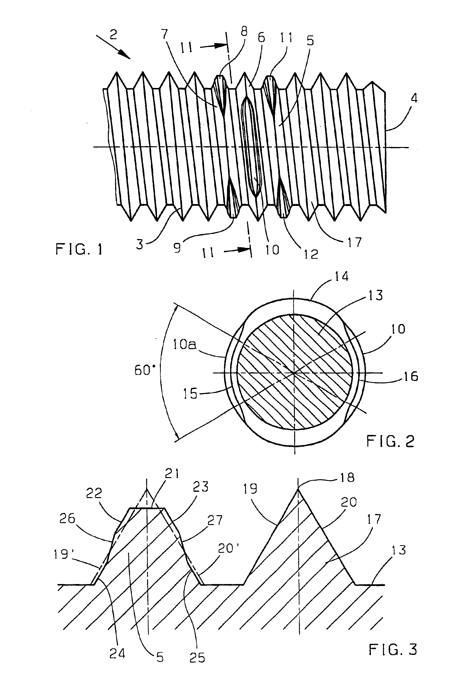
The compression of the thread turns in each region of the limited thread portion and the there resulting reduction of the outside diameter of the thread mean that, during the rolling of the screw, the necessary material is made available for the widening of the thread cross section in the outer region of the thread, said material then contributing particularly effectively to the aforementioned large-area contact in that region which is particularly effective in this regard, namely the outer region of the thread turns, where the greatest resistance to the further turning of the screw is particularly high owing to the there existing relatively large diameter. In order to achieve the desired locking effect to a high degree, only a relatively small increase of the thread cross section is required, depending on the hardness of the material for the screw or female thread, this making it possible, with regard to the deformation in the region of the limited thread portion or the opposite part of the female thread, to obtain only very small deformations in order to guarantee the required security. The aforementioned design, therefore, results, with relatively little effort as regards the rolling of the screw, in a high degree of security against further turning; that is, the screw has a high further turning moment.
Advantageously, the thread turns with limited thread portions are provided directly adjacent to each other, with the result that, in this case, the further turning moment is increased correspondingly quickly.
In the case of adjacent thread turns with limited thread portions, said thread portions are advantageously offset by 90° in relation to each other from thread turn to thread turn, as a result of which the pressure on the female thread is offset; that is, pressure on the female thread at the same places with regard to angle, i.e. at opposite places, is avoided.

Problems solved by technology

With the hitherto known screws with self-locking threads, it has been necessary, because of the design of the locking part, to accept that there will, to a considerable extent, be a plastic deformation, when the screw is screwed in, either of the female thread or of the thread of the locking part, this leading to difficulties, particularly in the case of hard materials for the screw or the female thread.

Method used


Image

  • Screw provided with self-locking thread
  • Screw provided with self-locking thread

Examples


Embodiment Construction

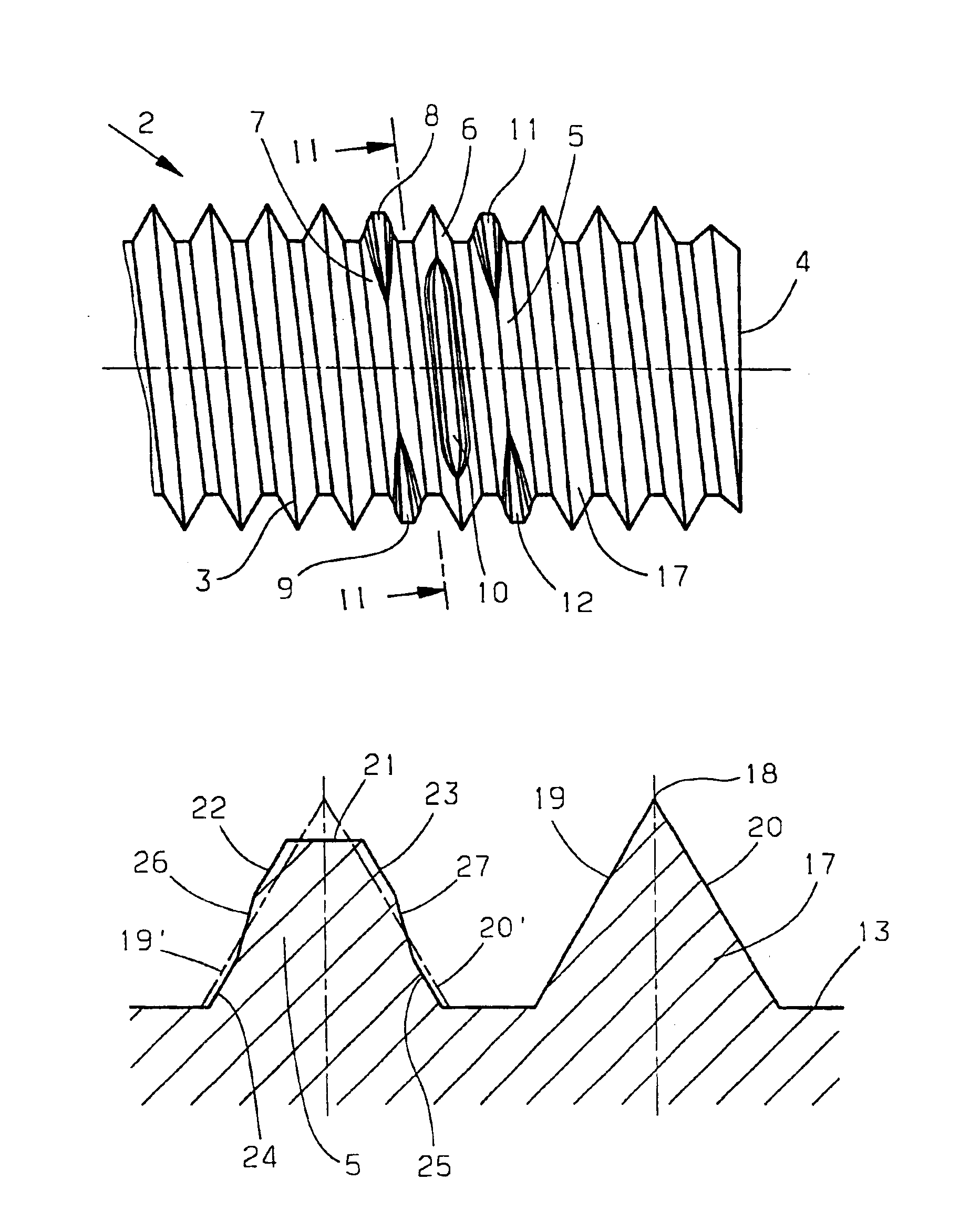
Apart from a screw head (not shown), the screw presented in FIG. 1 comprises the screw shank 2, which is provided continuously with the thread 3, which, therefore, extends as far as the thread beginning 4. Shown in the front half of the thread 3 are the thread turns 5, 6 and 7, which are provided with the limited thread portions 8 and 9, 10 as well as 11 and 12. The special design of said limited thread portions is explained in detail with reference to FIG. 3.

The limited thread portions 8, 9, 10, 11 and 12 serve to provide the screw with a desired self-locking effect when being screwed into a female thread, for which purpose the limited thread portions are of a special design. Said design consists, among other things, in that, in the region of the limited thread portions 8, 9, 10, 11 and 12, the outside diameter of the thread is reduced by radial compression. The further special design features will be discussed in greater detail in connection with FIG. 3. The region of the thread 3...


PUM


Abstract

Screw provided with self-locking rolled thread, wherein, in a plurality of places along its extent, the thread is deformed in relation to the normal thread cross section in that the thread outside diameter is reduced by radial compression of limited thread portions, the area of the thread cross section being substantially identical to that of the undeformed thread. While maintaining the slant of the thread flanks, the thread cross section is symmetrically widened in the outer region and reduced in the adjoining inner region, the transition from the widened to the reduced thread cross section lying approximately in the centre of the respective thread flank, and the limited thread portion extends over two parts of a thread turn such that there result two symmetrically opposite thread portions each of approximately ⅙ of the thread turn.

Description

BACKGROUND AND SUMMARY OF THE INVENTIONThe invention relates to a screw provided with self-locking, rolled thread, wherein, in a plurality of places along its extent, said thread is deformed in relation to the normal thread cross section in that the thread outside diameter is reduced by radial compression of limited thread portions, the area of the thread cross section being substantially identical to that of the undeformed thread.Screws with self-locking threads are known in a variety of forms. For example, the turns of a male thread are, circularly about the thread root, bent away from the head end in the axial direction in order thereby to produce a special friction in relation to a female thread (DE-OS 2062342). DE-OS 2257112 describes a deformation, referred to as a rib, of the turn of a male thread, said rib extending over only a portion of a thread turn. In the case of a self-locking thread described in DE-PS 1575259, the flank angle is, circularly about the thread root, chan...

Claims


Application Information

Patent Timeline
Patent Type & Authority Patents(United States)
IPC IPC(8): F16B39/30F16B39/00
CPCF16B39/30Y10S411/938
Inventor KOENIG, GOTTFRIEDMENZ, WERNER
Owner EJOT GMBH & CO KB
Learn More