Paired electrical cable connector

a technology of electrical cables and connectors, which is applied in the direction of insulated conductors, flat/ribbon cables, contact members penetrating/cutting insulation/cable strands, etc., can solve the problems of troublesome connection of paired cables to wiring harnesses within narrow spaces, increase the number of electrical cables constituting wiring harnesses, and increase the weight of wiring harnesses

Inactive Publication Date: 2005-03-08
YAZAKI CORP
View PDF7 Cites 23 Cited by
  • Summary
  • Abstract
  • Description
  • Claims
  • Application Information

AI Technical Summary

Benefits of technology

In view of the aforementioned disadvantage, an object of the invention is to provide a paired cable and an electrical connector for connection of such paired electrical cable with ease. A

Problems solved by technology

Thus, the connection of the paired cable to the wiring harness within the narrow space has been a troublesome work.
Furthermore, a recent motor vehicle tends to have an increased number of electronic instruments according to users requests, which increases the number

Method used


Image

  • Paired electrical cable connector
  • Paired electrical cable connector
  • Paired electrical cable connector

Examples


first embodiment

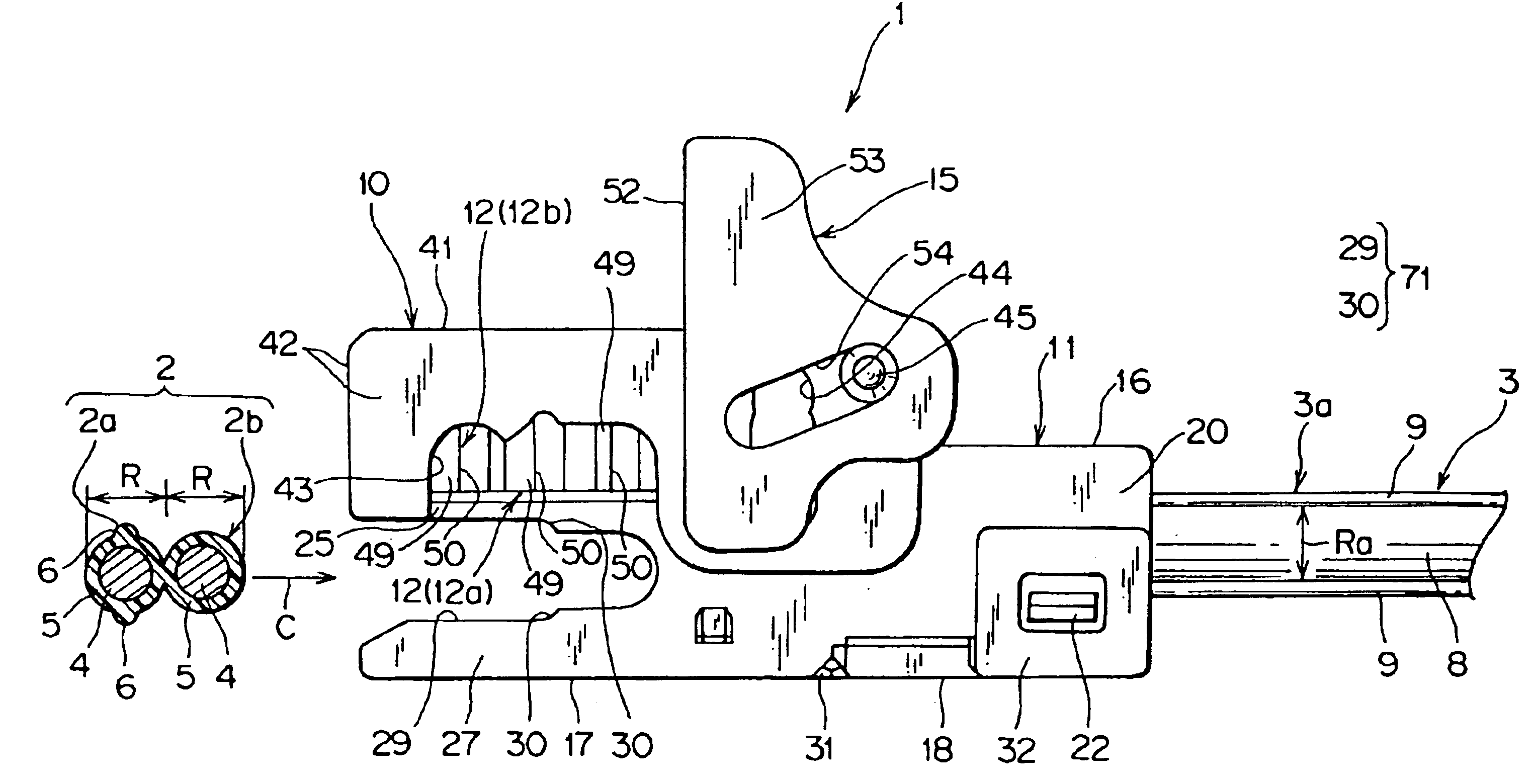
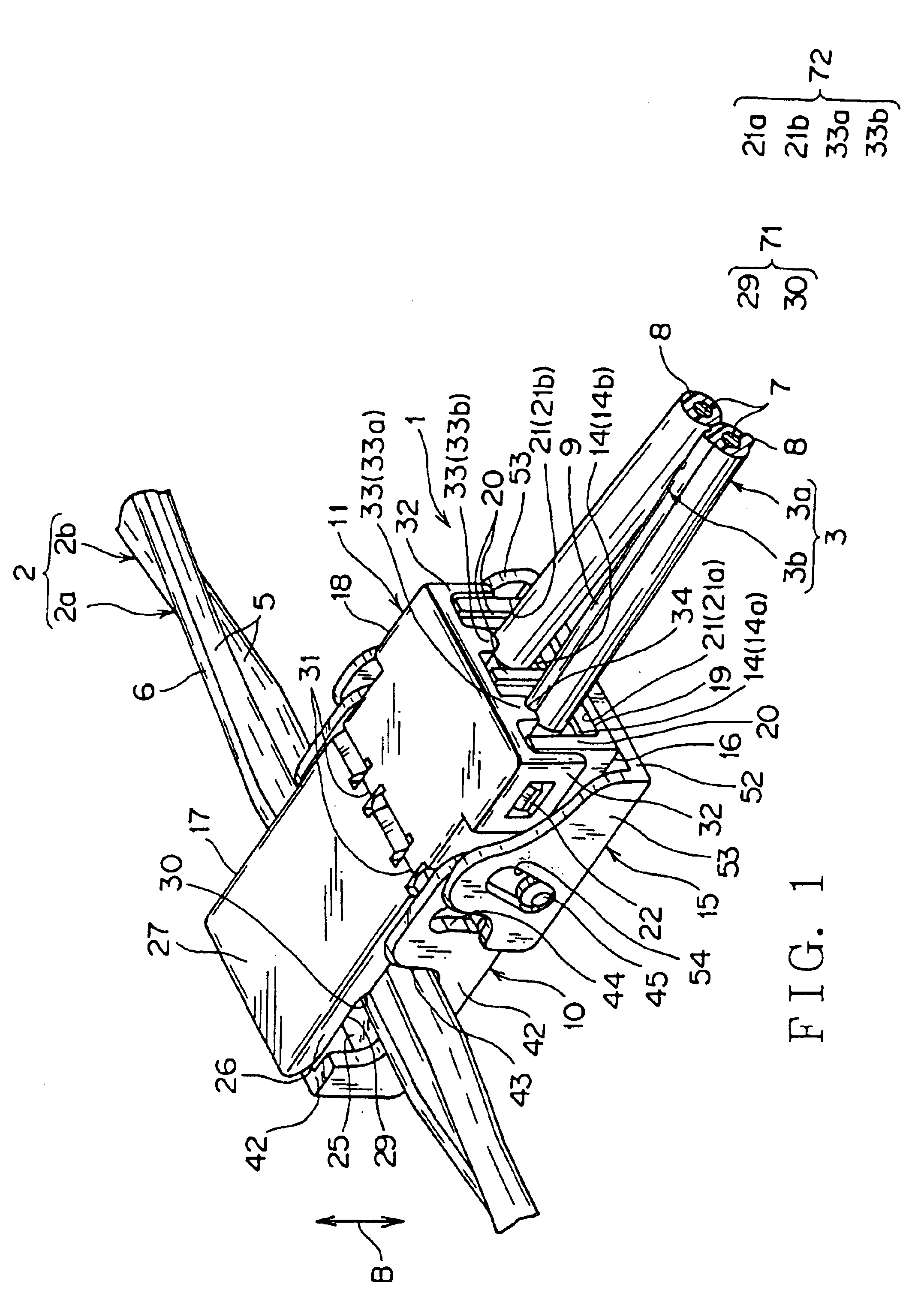
Referring to FIGS. 1 to 19, an electrical connector of a first embodiment according to the present invention will be discussed hereinafter. An electrical connector 1 shown FIG. 1 is used for electrically connecting a paired electrical cable 2, which is included in a wiring harness arranged in a motor vehicle, to an additional paired electrical cable 3 of an optional electronic instrument.

As best illustrated in FIG. 15, the paired electrical cable 2 has a pair of electrical cables 2a and 2b parallel to each other. Each of the cables 2a and 2b is a sheathed electrical cable having a wire core 4 and an insulating sheath 5 covering the wire core 4. The wire core 4 consists of electrically conductive metal wires, and the sheath 5 is made of a synthetic resin. One cable 2a has a diameter R (see FIG. 15) equal to that of the other cable 2b.

The one cable 2a is formed with a protrusion 6 radially projected from an outer surface of the sheath 5. In this embodiment, the protrusion 6 is extend...

second embodiment

For fitting the press-fit terminals 12a and 12b of the electrical connector 1 of the second embodiment to the cables 2a and 2b, a tool 60 shown in FIG. 21 is prepared. The tool 60 is a pair of pincers having a pinching part 61, a fulcrum 62, and an actuating part 63. The pinching part 61 has a pair of pincers 64 coming close to and apart from each other to pinch the electrical connector 1 therebetween. The fulcrum 62 pivotably supports the pair of pincers 64 coming close to and apart from each other. A worker moves the pair of actuating levers 65 to come close to each other so that the pair of pincers 64 come close to each other.

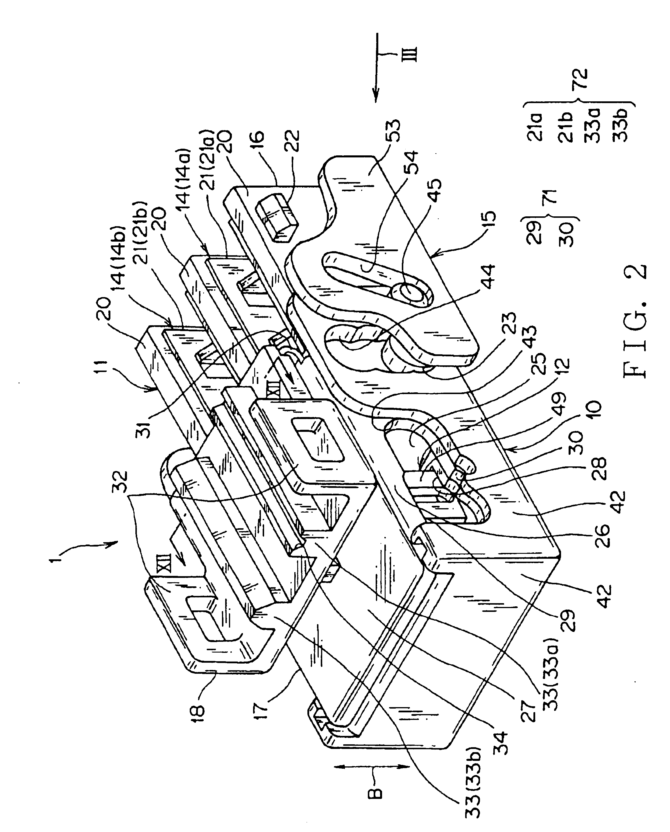
The electrical connector 1 of the second embodiment is assembled in the same way as the first embodiment. First, between the vertical walls 20 of the second connector housing 11, the press-fit terminals 14a and 14b are received. Meanwhile, the press-fit terminals 12a and 12b are fitted to the wall 41 of the first connector housing 10. The elongated hole 44 o...


PUM


Abstract

The electrical connector has a pair of first and second terminal fittings each connected to each of a pair of first and second electrical cables and a connector housing holding the terminal fittings. The electrical connector comprises a cable distinction device for electrically connecting the first electrical cable to the first electrical cable and the second electrical cable to the second electrical cable. The cable distinction device has a cutout with a shoulder, the cutout allowing insertion of the electrical cables into the connector housing, the shoulder positioned at a middle of an inner edge of the cutout, and the shoulder allows insertion of the first electrical cable but prevents insertion of the second electrical cable into the connector housing. The first and second electrical cables have an outer diameter equal to each other, and the first electrical cable has a protrusion projecting from an outer surface of a sheath to abut against the shoulder of the cutout when inserted in to the cutout. Alternatively, the first electrical cable may have an outer diameter larger than that of the second electrical, and the first electrical cable abuts against the shoulder of the cutout when inserted in to the cutout.

Description

BACKGROUND OF THE INVENTION1. Field of the InventionThe present invention relates to a paired electrical cable and a connector for the pair electrical cable.2. Related ArtA recent motor vehicle has various kinds of electronic instruments so that the vehicle is arranged with wiring harnesses for transmitting various signals and power to the electronic instruments of the vehicle. The wiring harness has a plurality of electrical cables and connectors joined to ends of the electrical cables for supplying various signals and power to the electronic instruments.For supplying various signals and power to the electronic instruments, there is provided a paired electrical cable consisting of two cables. One of the electrical cables transmits a signal and the other electrical cable transmits another signal which is opposite in phase. The paired cable decreases noise generated in the cables.Some motor vehicles have an optional electrical instrument according to a request of a user. This require...

Claims


Application Information

Patent Timeline
IPC IPC(8): H01R4/24H01R13/64H01B7/08H01R9/03
CPCH01R4/2433H01R13/64H01B7/0807H01R4/2454H01R12/616H01R9/031H01R4/2466
Inventor NEGISHI, SATOSHIUEDA, HIROHISA
Owner YAZAKI CORP
Why Eureka
Try Eureka