Synchronous generator for service in wind power plants, as well as a wind power plant

a technology for synchronous generators and wind power plants, which is applied in the direction of machines/engines, magnetic circuit rotating parts, magnetic circuit shape/form/construction, etc., can solve the problems of unwanted noise emission and the inability of conventional generators to achieve the required low noise emission, and achieve the effect of reducing noise, reducing cost, and reducing construction costs

Inactive Publication Date: 2005-03-08
WOBBEN ALOYS
View PDF25 Cites 24 Cited by
  • Summary
  • Abstract
  • Description
  • Claims
  • Application Information

AI Technical Summary

Benefits of technology

The invention is about a new design for a generator that reduces noise and matches voltage behavior. It also allows for a closer placement of adjacent pole pieces, which can be shaped like trapezoids to induce trapezoidal voltages. Trapezoidal voltages have a constant amplitude over an extended time period, which eliminates the need for expensive direct current filters. The generator also reduces stray-field losses and vibrations. Overall, the design improves the performance and efficiency of generators.

Problems solved by technology

The technical problem addressed in this patent is the high noise emissions generated by conventional generators used in wind power plants due to strong mechanical vibrations during operation. The objective is to provide a method and generator design that eliminate these problems and improve the overall acceptance of wind power plants.

Method used


Image

  • Synchronous generator for service in wind power plants, as well as a wind power plant
  • Synchronous generator for service in wind power plants, as well as a wind power plant
  • Synchronous generator for service in wind power plants, as well as a wind power plant

Examples


Embodiment Construction

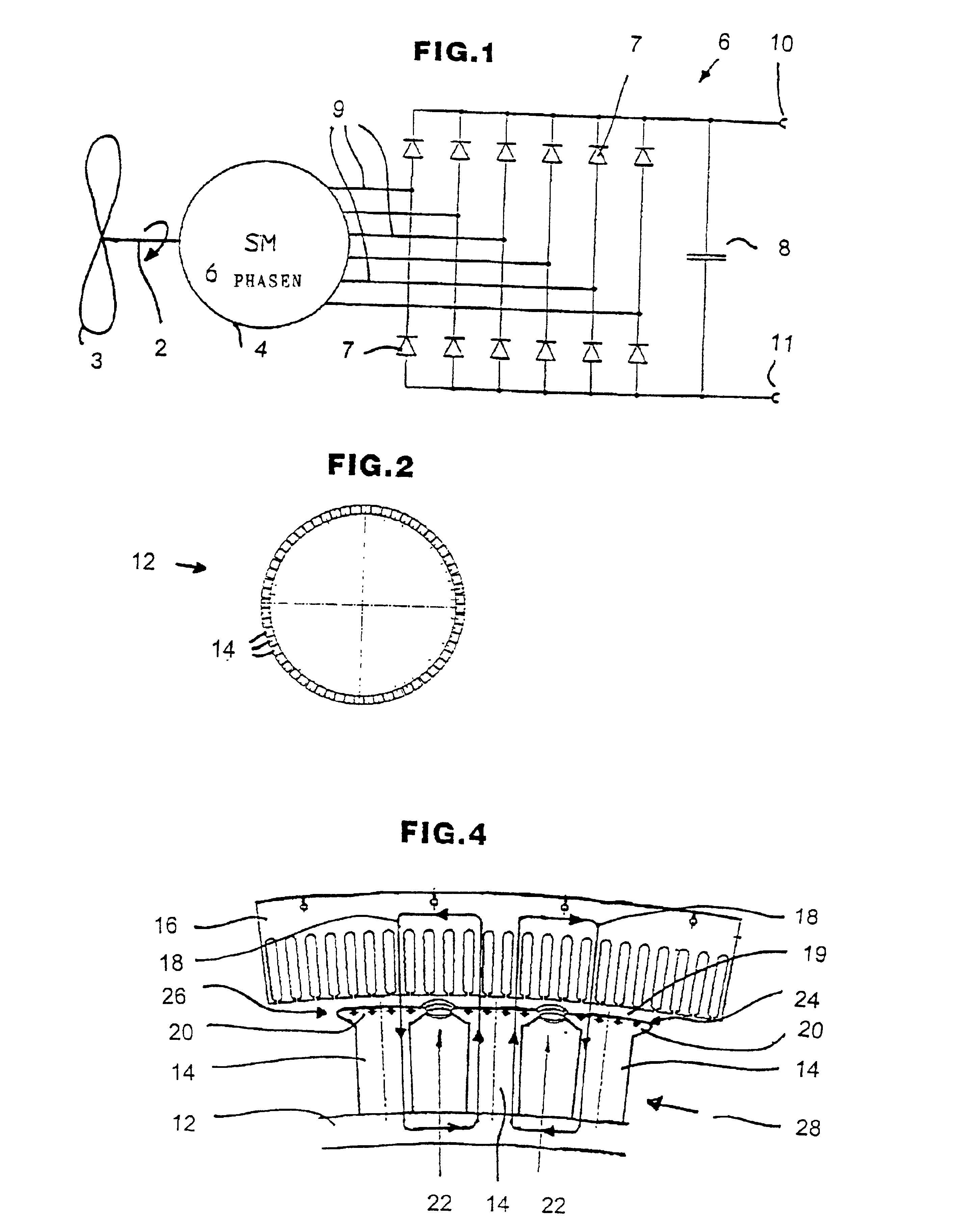
FIG. 1 shows a schematic representation of this invention's wind power plant with a synchronous generator.

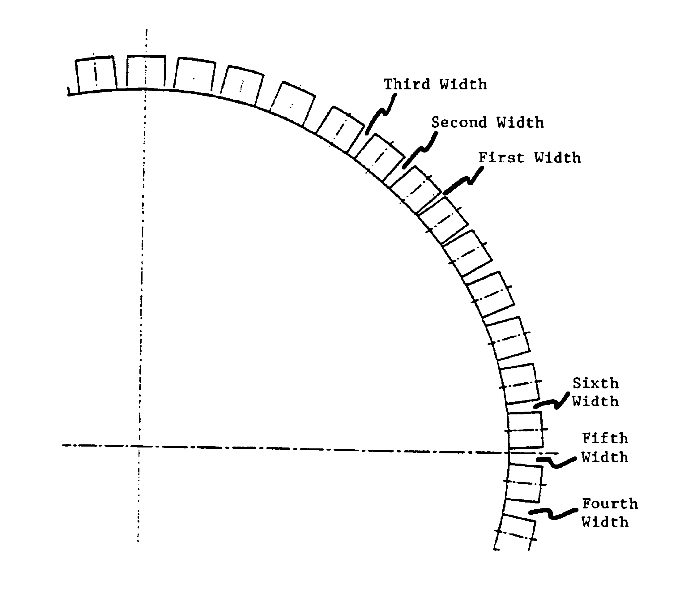
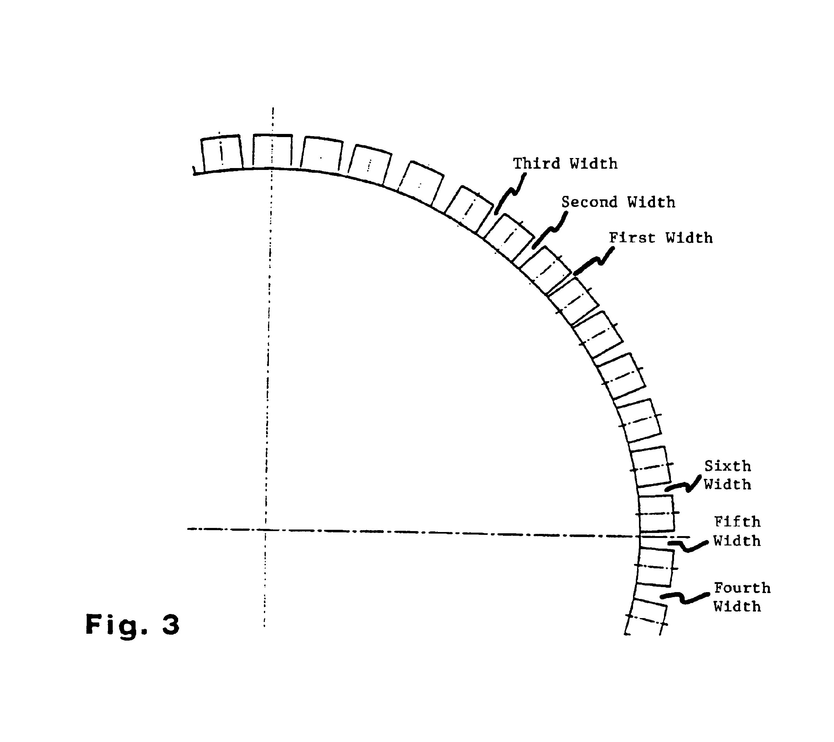
FIG. 2 shows a schematic representation of a generator rotor with variable distances between the pole shoes or pole pieces.

FIG. 3 shows an enlarged section of the rotor of FIG. 2.

FIG. 4 shows a schematic of a section of a rotor and a stator of the synchronous generator.

FIG. 5 shows a lateral view of the pole of a rotor according to this invention.

FIG. 6 shows a top view of the pole of FIG. 5.

FIG. 7 shows a top view of this invention's pole, as well as a related diagram of stator voltage versus time.

FIG. 8 shows a further diagram of stator voltage versus time.

FIG. 9 shows a further diagram of stator voltage versus time.

FIG. 10 shows a schematic representation of the stator winding as a 6-phase winding.

FIG. 11 shows a graph of force versus distance for conventional synchronous generators, illustrating the response of the tangential force along the circumference of a stator slot.

FI...


PUM


Abstract

A synchronous generator comprising a stator and a motor movable relative to the stator. The generator contains a plurality of poles for generating electrical energy. The time behavior of the voltage induced in one or several stator windings essentially approximates the current time behavior in one stator winding or the sum of at least several component currents. The poles are positioned asymmetrically on the rotor.

Description


Claims


Application Information

Patent Timeline
Owner WOBBEN ALOYS
Why Eureka
Try Eureka