Radar system using random RF noise

a random noise and radar technology, applied in the field of radars, can solve the problems of affecting the performance of radars, and signals transmitted by radars can interfere with the functioning of other electronic devices,

Inactive Publication Date: 2005-03-08
OHIO STATE INNOVATION FOUND
View PDF11 Cites 30 Cited by
  • Summary
  • Abstract
  • Description
  • Claims
  • Application Information

AI Technical Summary

Benefits of technology

In addition to the novel features and advantages mentioned above, other features and advantages of the pres...

Problems solved by technology

Despite the many benefits, conventional radars have a number of significant drawbacks.
For instance, obstructions such as buildings, foliage, and other types of structures or vegetation may impede the performance of a radar by blocking or deflecting the signals transmitted by the radar.
In addition, the signals...

Method used


Image

  • Radar system using random RF noise
  • Radar system using random RF noise
  • Radar system using random RF noise

Examples


examples

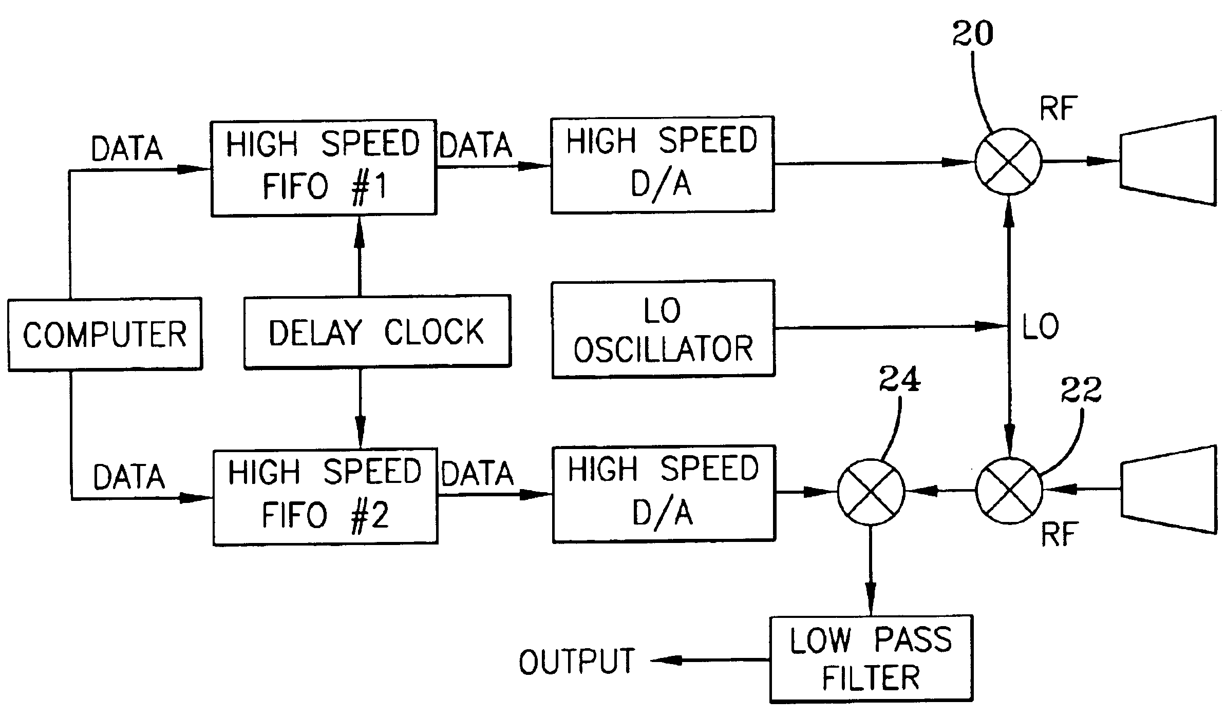
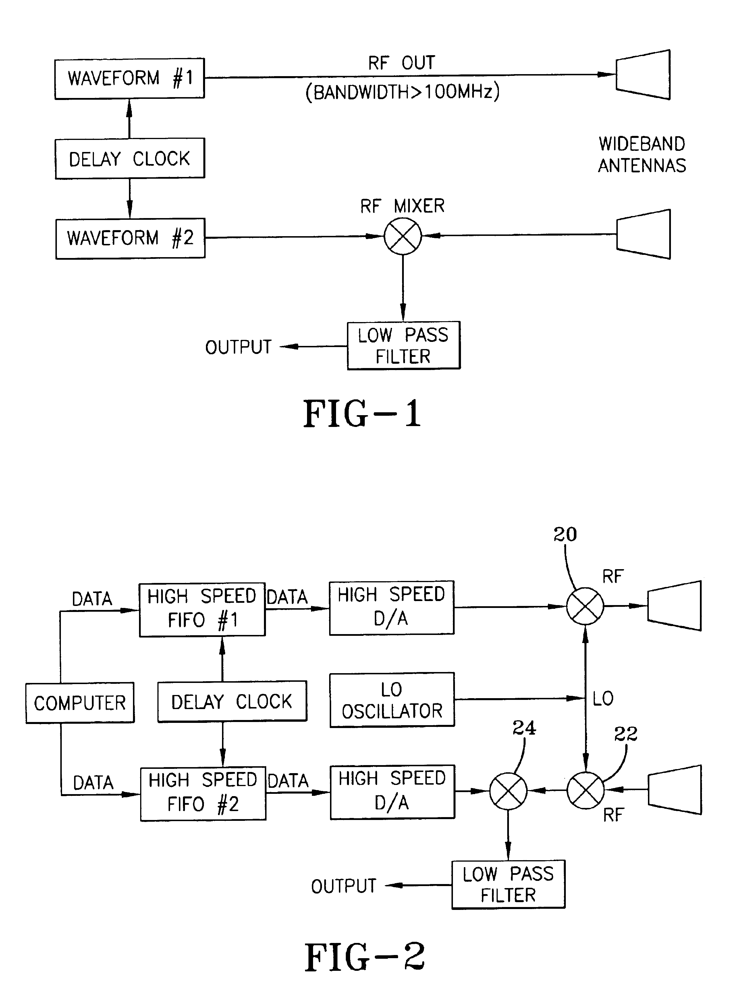
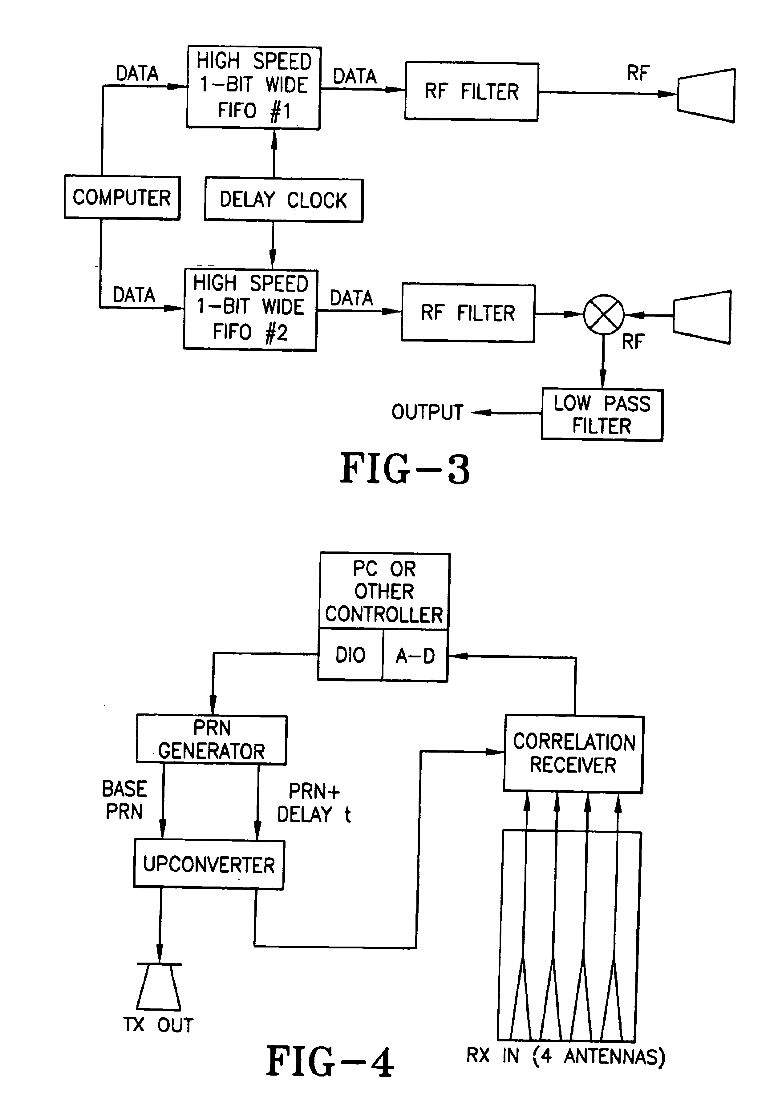
An exemplary embodiment of a stealthy noise radar for vehicle obstacle avoidance was built. This example of the noise radar achieved stealth by using a noise-like (pseudorandom) waveform with more than 700 MHz of bandwidth. The radar used parallel analog correlation cross correlation for receiving. This provided protection from jamming (accidental due to local communications transmitters or deliberate) as well as mitigation of interference caused by the radar. Several radars of the same design can be operated in the vicinity of each other without interfering each other.

The radar was mounted on a stationary support and tested in a foliage environment. It showed that it can detect, range, and / or classify obstacles such as humans, cinder blocks, metal cylinders, various size trees, tree stumps, rocks, and holes. In particular, this embodiment could detect humans to 250 feet and small trees to 350 feet.

The radar, for example, may use a single steered-beam antenna or a multi-beam antenna...


PUM


Abstract

A radar system that utilizes predetermined, pseudorandom, or random waveforms that may be substantially matched to the impulse response of the radar and any surrounding clutter such that the signal-to-clutter ratio may be optimized and/or such that specific targets may be identified and/or classified.

Description

BACKGROUND OF THE INVENTIONThe present invention relates generally to radars. More particularly, the present invention relates to a noise radar. For instance, an exemplary embodiment of the present invention may use transmitted noise in the radio frequency (RF) range. As used herein, the term “noise” shall be understood random noise as well as pseudorandom noise.Radars are used for a variety of purposes. For example, radars are used to detect the speed at which a target (e.g., a vehicle, a ball, a person, etc.) is traveling. Radars, such as in security systems, are also used to detect other types of movement. In addition, radars are also used to determine the presence of a target.Despite the many benefits, conventional radars have a number of significant drawbacks. For instance, obstructions such as buildings, foliage, and other types of structures or vegetation may impede the performance of a radar by blocking or deflecting the signals transmitted by the radar. In addition, the sig...

Claims


Application Information

Patent Timeline
IPC IPC(8): G01S13/34G01S13/00G01S7/02G01S7/35G01S13/02G01S13/93G01S13/931
CPCG01S7/023G01S7/35G01S13/346G01S2013/0281G01S13/931G01S7/0234G01S7/0235
Inventor WALTON, ERIC K.
Owner OHIO STATE INNOVATION FOUND
Why Eureka
Try Eureka