Low profile wideband antenna array

a wideband antenna array, low-profile technology, applied in the direction of linear waveguide fed arrays, antennas, antenna adaptation in movable bodies, etc., can solve the problem of limited bandwidth to about 5 percent, and achieve the effect of wide bandwidth and low profil

Inactive Publication Date: 2005-03-08
RAYTHEON CO
View PDF7 Cites 173 Cited by
  • Summary
  • Abstract
  • Description
  • Claims
  • Application Information

AI Technical Summary

Benefits of technology

The present invention teaches how to make a multichannel radar antenna that has a low profile and a wide bandwidth. The antenna is made with a series of channels that function as an array of open, parallel plate waveguides. Each channel includes at least one wave launcher. The channels are placed side-by-side to form a phased array. The wave launchers may be coaxial cables individually connected to the channels. Alternatively, the wave launchers may be fabricated from a pair of circuit cards with electrically conductive strip lines that form the electric equivalent of coaxial cables. The cards forming wave launchers and the cooperative metal channels can take a variety of forms. The channels may be open to the atmosphere, or they may be filled with a dielectric. The array may be flat or curved in one or two directions.

Problems solved by technology

They are even shallower than slot elements, but are also limited to about 5 percent bandwidth.

Method used


Image

  • Low profile wideband antenna array
  • Low profile wideband antenna array
  • Low profile wideband antenna array

Examples


Embodiment Construction

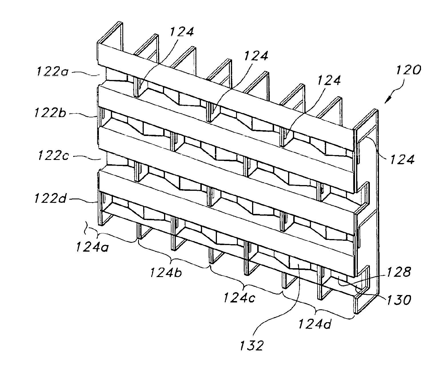
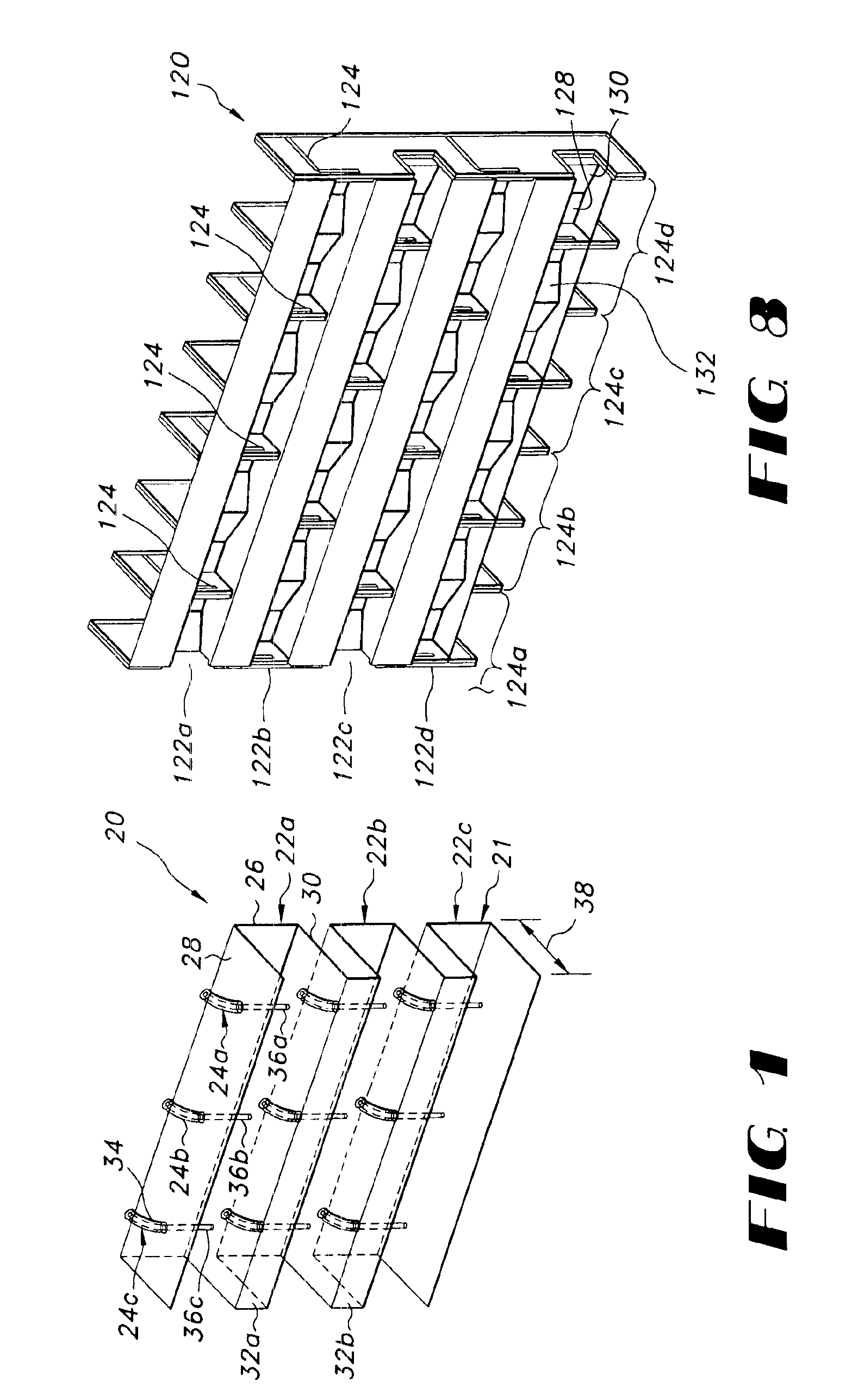
FIG. 1 shows a phased array radar antenna 20 utilizing the present invention. The antenna 20 in FIG. 1 has a metal structure 21 that forms three approximately horizontally extending channels 22a, 22b, 22c. In FIG. 1 the channels 22a, b and c are positioned one on top of the other and extend from left to right in the Figure. Each channel 22 includes at least one wave launcher 24, and illustrated each channel 22 has three wave launchers 24a, 24b, 24c. The channels 22 and wave launchers 24 therefore form a 3×3 array of parallel plate resonators.

Phased array antennas in general are constructed of identical wave launchers and cavities that are arranged in a predetermined (usually regular) array. In this application elements that are identical except for their location are given the same reference numerals with a letter suffixed. Similarly, to avoid unnecessary detail in many places this application describes in detail only one element or combination of elements. The other elements that d...


PUM


Abstract

A phased array antenna having a low profile (approximately ⅛ wavelength) wide bandwidth (approximately 50%). The invention teaches making such an antenna using open channel resonators and monopole wave launchers. The wave launchers may conveniently be made on circuit card assemblies with strip lines that mimic coaxial cable monopole wave launchers. The channel resonators may be made in sections that are soldered to the circuit card assemblies. The circuit card assemblies have plated through holes that trace the edges of the resonator sections to provide electrical continuity.

Description

BACKGROUND OF THE INVENTIONA large number of antenna applications require low-profile antenna arrays that can be flush-mounted in or on a structure. Such antennas are usually referred to as “conformal array antennas.” The designs available until now that are thin have been narrow band, permitting use only over a narrow range of frequencies. Conversely, those previously known antennas that are wide band have been thick, with excessive intrusion into, or protrusion from, the supporting structure.Waveguide slots are one of the most common radiating elements used for low-profile array antennas. They are typically less than 0.25 wavelengths deep, but their bandwidth is only about 5 percent. Microstrip patch elements are another popular choice. They are even shallower than slot elements, but are also limited to about 5 percent bandwidth. In contrast, wide band radiating elements such as notches are usually about one wavelength deep.SUMMARY OF THE INVENTIONThe present invention teaches how...

Claims


Application Information

Patent Timeline
Patent Type & Authority Patents(United States)
IPC IPC(8): H01Q21/00H01Q21/06
CPCH01Q21/0037H01Q21/062H01Q21/061H01Q21/0075
Inventor MCGRATH, DANIEL T.
Owner RAYTHEON CO
Why Eureka
Try Eureka