
Dish antenna rotation apparatus

a technology of rotating apparatus and antenna, which is applied in the direction of collapsible antenna means, antenna details, antennas, etc., can solve the problems of troublesome manufacture of rotating apparatus, and achieve the effect of expanding the same angular length

Inactive Publication Date: 2005-03-08
DX ANTENNA CO LTD
View PDF5 Cites 70 Cited by
  • Summary
  • Abstract
  • Description
  • Claims
  • Application Information

AI Technical Summary

Benefits of technology

[0006]The dish antenna rotation apparatus according to the present invention includes an antenna bracket. The antenna bracket is adapted to be secured to the rear surface of a reflector of a dish antenna, e.g. an offset parabolic antenna. The antenna bracket has a planar plate having opposing major surfaces which, when the antenna bracket is secured to the reflector, lie perpendicular to a “polarity axis”. The polarity axis referred to herein is an ax

Problems solved by technology

This makes it troublesome to manufacture the rotation apparatus.

Method used


Image

  • Dish antenna rotation apparatus
  • Dish antenna rotation apparatus
  • Dish antenna rotation apparatus

Examples


Embodiment Construction

[0013]FIG. 3 is a rear perspective view of part of the antenna of FIG. 1.

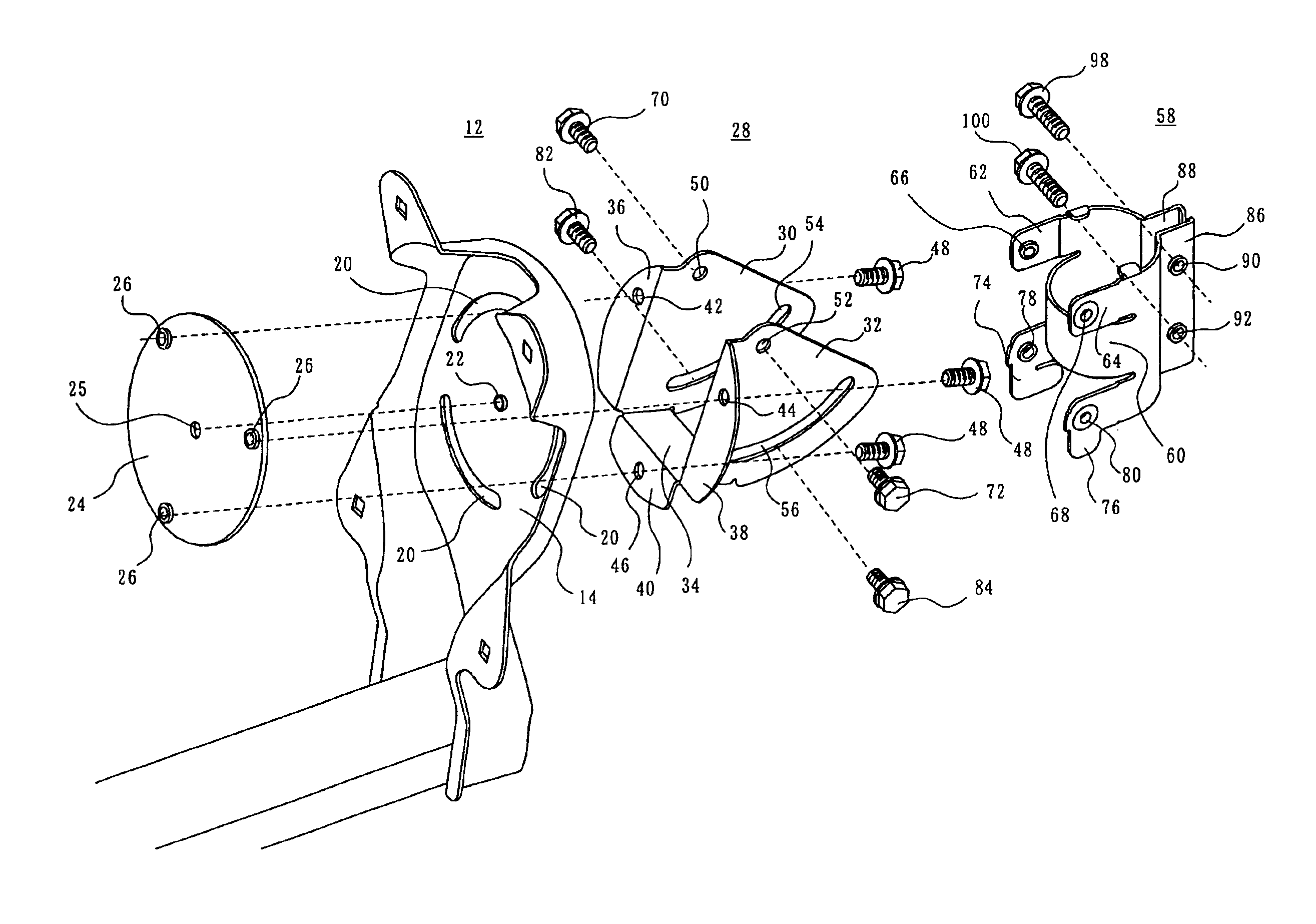
[0014]FIG. 4 is an exploded view of the dish antenna rotation apparatus shown in FIG. 1.

[0015]FIG. 5 shows a longitudinal cross-section of part of the antenna of FIG. 1.

BEST MODE OF THE INVENTION

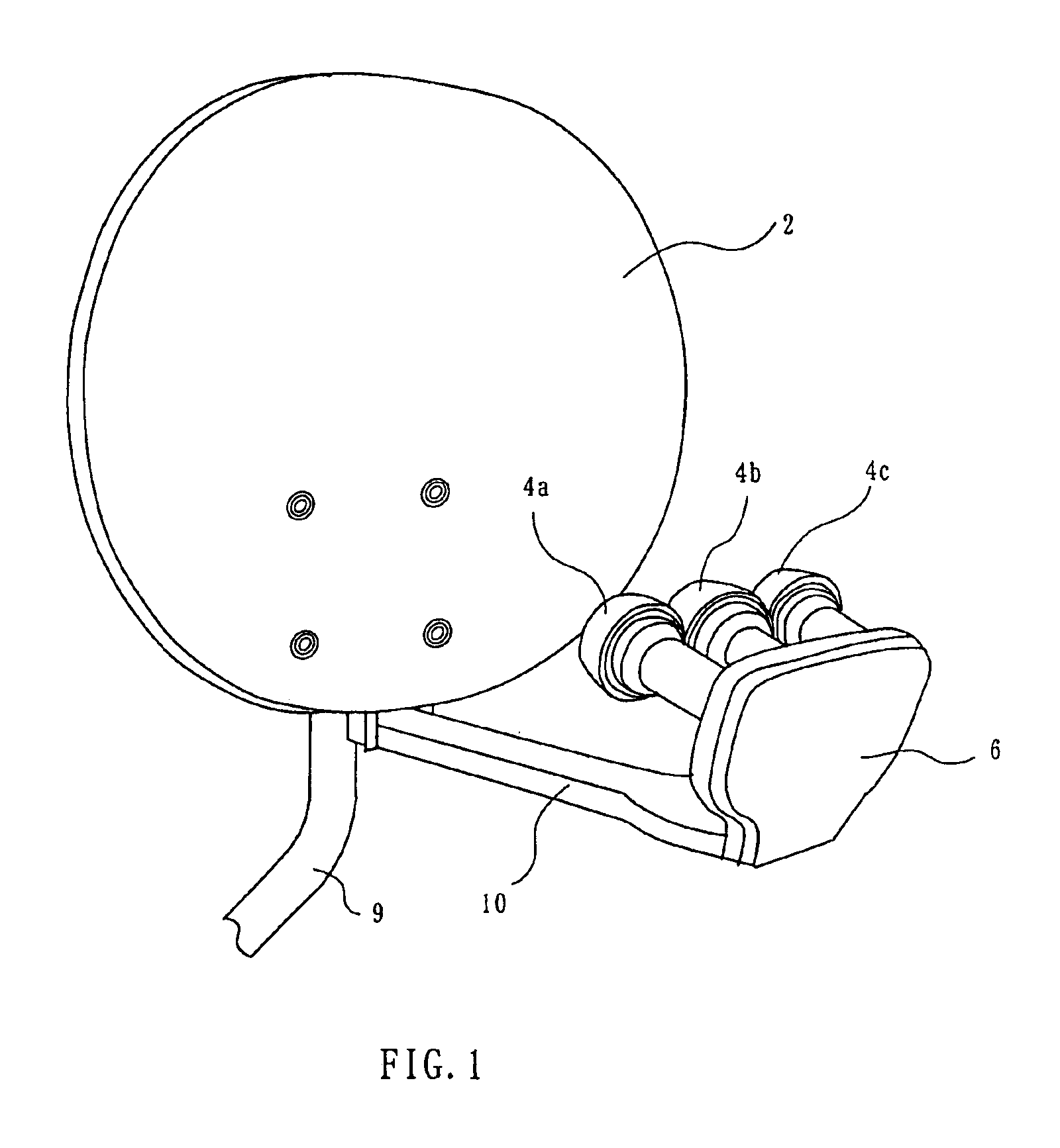
[0016]A dish antenna with an antenna rotation apparatus according to an embodiment of the present invention may be a multi-beam antenna as shown in FIG. 1. The multi-beam antenna includes an offset parabolic reflector 2, and a low noise block converter 6 with plural, e.g. three, primary radiators 4a, 4b and 4c disposed in the vicinity of the focal point of the reflector 2. The three primary radiators 4a, 4b and 4c are for three stationary satellites, e.g. broadcasting satellites, at locations in the space defined by given longitudes and latitudes, for example, at locations above the equator.

[0017]A rotation, elevation and azimuth adjustment apparatus 8 for allowing adjustment of the rotation, elevation, and azimuth of t...


PUM


Abstract

A bracket (12) is fixed to the rear surface of a reflector (2). The bracket has a planar plate (14) which, when the bracket is fixed to the reflector, is perpendicular to a polarity axis (16). Plural, spaced-apart arcuate slots (20) arranged on an imaginary circle on the planar plate (14) about the polarity axis (16) are formed in the planar plate (14). An adapter plate (24) is disposed in contact with the surface of the planar plate (14) facing the reflector (2). The bracket (12) is rotatable about the polarity axis (16) relative to the adapter plate (24). The adapter plate (24) has screw holes (26) in alignment with the arcuate slots (20) in the planar plate (14). A bracket (28) is disposed on the side of the planar plate (14) opposite to the reflector (2). The bracket (28) has a pair of wings (30, 32). A connecting member (34) is formed integral with the wings (30, 32). The connecting member (34) is perpendicular to the wings (30, 32). The bracket (28) is rotatable about an elevation adjustment axis passing between the wings (30, 32). The bracket (28) has tabs (36, 38, 40). The tabs (36, 38, 40) are adapted to contact the planar plate (14) and provided with respective holes (42, 44, 46). Bolts (48) are inserted through the respective holes (42, 44, 46) and the respective arcuate slots (20) and screwed into the screw holes (26) in the adapter plate (24), whereby the brackets (12, 28) are secured to the adapter plate (24).

Description

[0002]This invention relates to a dish antenna rotation apparatus which allows adjustment of the rotation angle of a dish antenna.BACKGROUND OF THE INVENTION[0003]A multi-beam antenna may be used to receive signals from a plurality of stationary satellites, such as communications satellites and broadcasting satellites. A multi-beam antenna uses a multi-beam antenna rotation apparatus for adjusting the antenna to predetermined elevational, azimuth and rotation angles. An example of such multi-beam antenna rotation apparatus is disclosed in, U.S. Pat. No. 6,445,361 which issued on Sep. 3, 2002.[0004]The antenna rotation apparatus disclosed in U.S. Pat. No. 6,445,361 includes a dish bracket, an elevation bracket and azimuth clamp. The dish bracket is fixed to the back of the dish antenna. A plurality of spaced-apart arcuate slots are formed in the dish bracket, being arranged on an imaginary circle drawn on the dish bracket. The dish bracket is provided with a projection at the center ...

Claims


Application Information

Patent Timeline
IPC IPC(8): H01Q1/12H01Q3/02H01Q1/08H01Q19/17
CPCH01Q19/17H01Q1/125
Inventor FUJITA, KENICHI
Owner DX ANTENNA CO LTD
Learn More