
Metal-enclosed switchgear

Active Publication Date: 2005-03-08
MITSUBISHI ELECTRIC CORP
View PDF15 Cites 33 Cited by
  • Summary
  • Abstract
  • Description
  • Claims
  • Application Information

AI Technical Summary

Benefits of technology

[0012]In view of the foregoing, it is an object of the invention to provide a metal-enclosed switchgear of which tank can be reduced in size by eliminating the need for insulators for fitting bus-side conductor strips on an inner wall of a tank.
[0014]This construction makes it possible to eliminate the need for the provision of insulators for supporting bus-side conductor strips and thereby serves to reduce the size of the metal-enclosed switchgear.

Problems solved by technology

One problem of conventional metal-enclosed switchgear systems is that it is difficult to reduce their physical size because there are provided insulators and other fittings for supporting the bus side conductor strips on the inner wall of the tank as stated above.
This makes it difficult to reduce the width of the conventional metal-enclosed switchgear, or its depth as illustrated in FIG. 3 appended to the aforementioned Patent Publication No. 1999-185577.
More specifically, three insulators are arranged side by side in a horizontal plane in the metal-enclosed switchgear of the Publication, so that its width inevitably increases if insulators having a large diameter is used.
Taking into account the fact that a specific amount of installation space should be allowed around each insulator, it is even more difficult to reduce the width of the metal-enclosed switchgear.

Method used


Image

  • Metal-enclosed switchgear
  • Metal-enclosed switchgear
  • Metal-enclosed switchgear

Examples


first embodiment

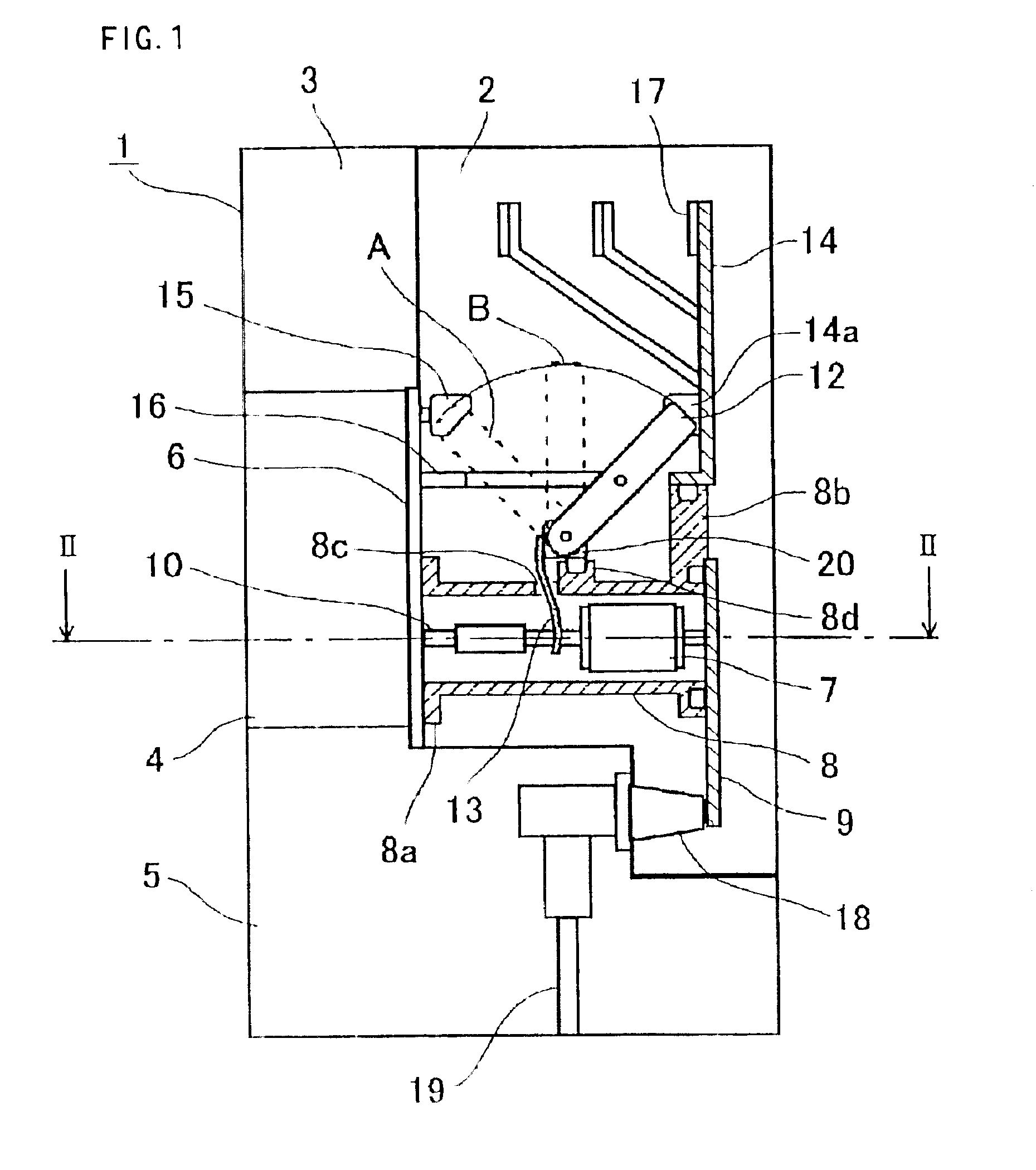
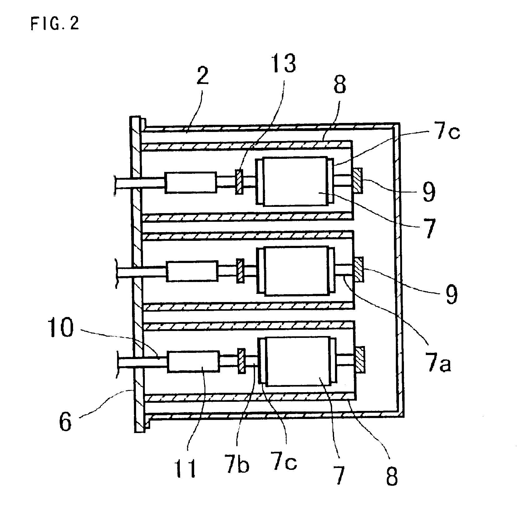
[0038]FIG. 1 is a schematic sectional side view of a metal-enclosed switchgear according to a first embodiment of the invention, and FIG. 2 is a sectional diagram showing principal parts f the metal-enclosed switchgear taken along lines II—II of FIG. 1.

[0039]The metal-enclosed switchgear has a metallic container 1 of which left side is the front and right side is the rear as illustrated in FIG. 1. The interior of the metallic container 1 is partitioned into multiple sections. These are a tank 2 filled with an insulating gas that is located at an upper rear part, a control compartment 3 located at an upper front part, an actuator mechanism compartment 4, located below the control compartment 3 in a central front part and a cable compartment 5 located at a lowermost part.

[0040]At a lower part of the tank 2, there are provided three insulator tubes 8 arranged side by side in a horizontal plane. These insulator tubes 8 accommodate vacuum-valve breakers 7 for individual phases of a power...

second embodiment

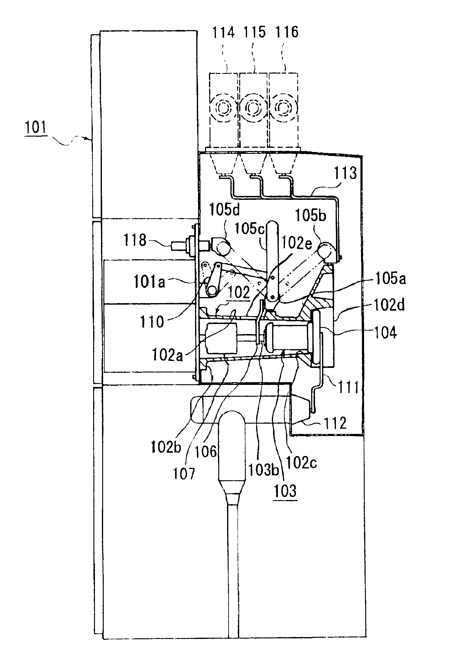
[0056]FIG. 3 is a sectional diagram showing principal parts of a metal-enclosed switchgear according to a second embodiment of the invention, FIG. 4 is a sectional diagram showing the entire metal-enclosed switchgear, FIG. 5 is a perspective view of one of generally cylindrical insulator housings 102 serving as insulator tubes, FIG. 6 is an elevational view of the cylindrical insulator housing 102 of FIG. 5 as it is seen from the side of an open end portion 102c, and FIG. 7 is a perspective view showing how the cylindrical insulator housings 102 for three phases are arranged.

[0057]Referring to FIGS. 3 and 4, the metal-enclosed switchgear has a sealed enclosure (metallic enclosure) 101 in which the individual cylindrical insulator housings 102 are fixed side by side. Made of an insulating material such as epoxy resin, each cylindrical insulator housing 102 has a cylindrical portion 102a and a flange portion 102b formed at one end of the cylindrical portion 102a. There is provided a s...

third embodiment

[0112]FIG. 16 is a perspective view of a one of generally cylindrical insulator housings 122 used in a metal-enclosed switchgear according to a third embodiment of the invention, and FIG. 17 is a cross section of the cylindrical insulator housing 122 of FIG. 16 particularly showing its side opening 102e and a flexible conductor 106. In this embodiment, each cylindrical insulator housing 122 has a cylindrical portion 102a and a second insulating barrier 102h one-piece formed with the cylindrical portion 102a along edges of the side opening 102e to cover at least part of the periphery of the flexible conductor 106. Although not illustrated in FIG. 16, a disconnector 105 of the same structure as that of FIG. 3 is provided at the same location. The metal-enclosed switchgear of this embodiment has otherwise the same construction as that of the second embodiments.

[0113]As shown in FIG. 17, the second insulating barrier 102h has a height D2 as viewed along the longitudinal axis of the cyli...


PUM


Abstract

A tank filled with an insulating gas accommodates insulator tubes incorporating vacuum-valve breakers for individual phases. One end of each insulator tube is fixed to the inside of the tank. Each vacuum-valve breaker is installed generally on a common longitudinal axis with the corresponding insulator tube so that a movable electrode rod is directed toward a fixed end of the insulator tube. The insulator tube has as an integral part a bus line fixing portion projecting in a direction intersecting the longitudinal axis of the insulator tube from the proximity of an end opposite to the fixed end, supporting a bus-side conductor in an insulated fashion.

Description

BACKGROUND OF THE INVENTION[0002]1. Field of the Invention[0003]The present invention relates to a metal-enclosed switchgear using vacuum-valve breakers.[0004]2. Description of the Background Art[0005]A conventional metal-enclosed switchgear using vacuum-valve breakers is provided with fittings, such as insulators, for supporting bus-side conductor strips on an inner wall of a sealed tank filled with an insulating gas as disclosed in Japanese Laid-open Patent Publication No. 1999-185577, for example.[0006]One problem of conventional metal-enclosed switchgear systems is that it is difficult to reduce their physical size because there are provided insulators and other fittings for supporting the bus side conductor strips on the inner wall of the tank as stated above.[0007]The insulators used in a metal-enclosed switchgear should meet at least the following two requirements:[0008](1) The insulator should withstand an electromagnetic impact force exerted by the bus-side conductor strips...

Claims


Application Information

Patent Timeline
IPC IPC(8): H01H33/66H01H33/666H02B13/035H01H33/12H01H33/04H01H33/22H02B13/02H01H1/58H01H31/00H01H33/02H01H33/56
CPCH02B13/0354H01H33/6661H01H1/5822H01H31/003H01H33/022H01H33/122H01H33/56H01H2033/6665H01H33/22H02B13/02
Inventor SATO, SHINJITSURIMOTO, TAKAOKOYAMA, KENICHIARIOKA, MASAHIRO
Owner MITSUBISHI ELECTRIC CORP
Features
  • Generate Ideas
  • Intellectual Property
  • Life Sciences
  • Materials
  • Tech Scout
  • Unparalleled Data Quality
  • Higher Quality Content
  • 60% Fewer Hallucinations
Learn More