Termination assembly for use in optical fiber hydrophone array

Inactive Publication Date: 2005-03-08
GENERAL DYNAMICS MISSION SYST INC
View PDF83 Cites 75 Cited by
  • Summary
  • Abstract
  • Description
  • Claims
  • Application Information

AI Technical Summary

Benefits of technology

The present invention is for use in an optical hydrophone module, and more specifically, at the ends of modules. A termination assembly according to the present invention provides a means for filling individual modules with fill fluid, as well as providing a hydrostatic module and optical fiber seal at the forward and aft bulkhead coupling within a modul

Problems solved by technology

While large bandwidth capabilities and small size make optical fibers desirable for use, optical fibers are mechanically fragile.
Tow-induced loads may cause the fibers to fracture.
Radial compressive loads may cause degraded light transmission as the result of a phenomenon known as microbending loss.
Stress corrosion is another cause of failure of optical fibers, and is a stress-accelerated chemical reaction between the opti

Method used


Image

  • Termination assembly for use in optical fiber hydrophone array
  • Termination assembly for use in optical fiber hydrophone array
  • Termination assembly for use in optical fiber hydrophone array

Examples


Embodiment Construction

Certain terminology is used herein for convenience only and is not to be taken as a limitation on the invention. For example, words such as forward, aft, upper, lower, left, right, horizontal, vertical, upward, and downward merely describe the configuration shown in the Figures. The components may be oriented in any direction and the terminology, therefore, should be understood as encompassing such variations unless specified otherwise. Also, the scope of the invention is not intended to be limited by the materials or dimensions listed herein, but may be carried out using any materials and dimensions that allow the construction and operation of the hydrophone module.

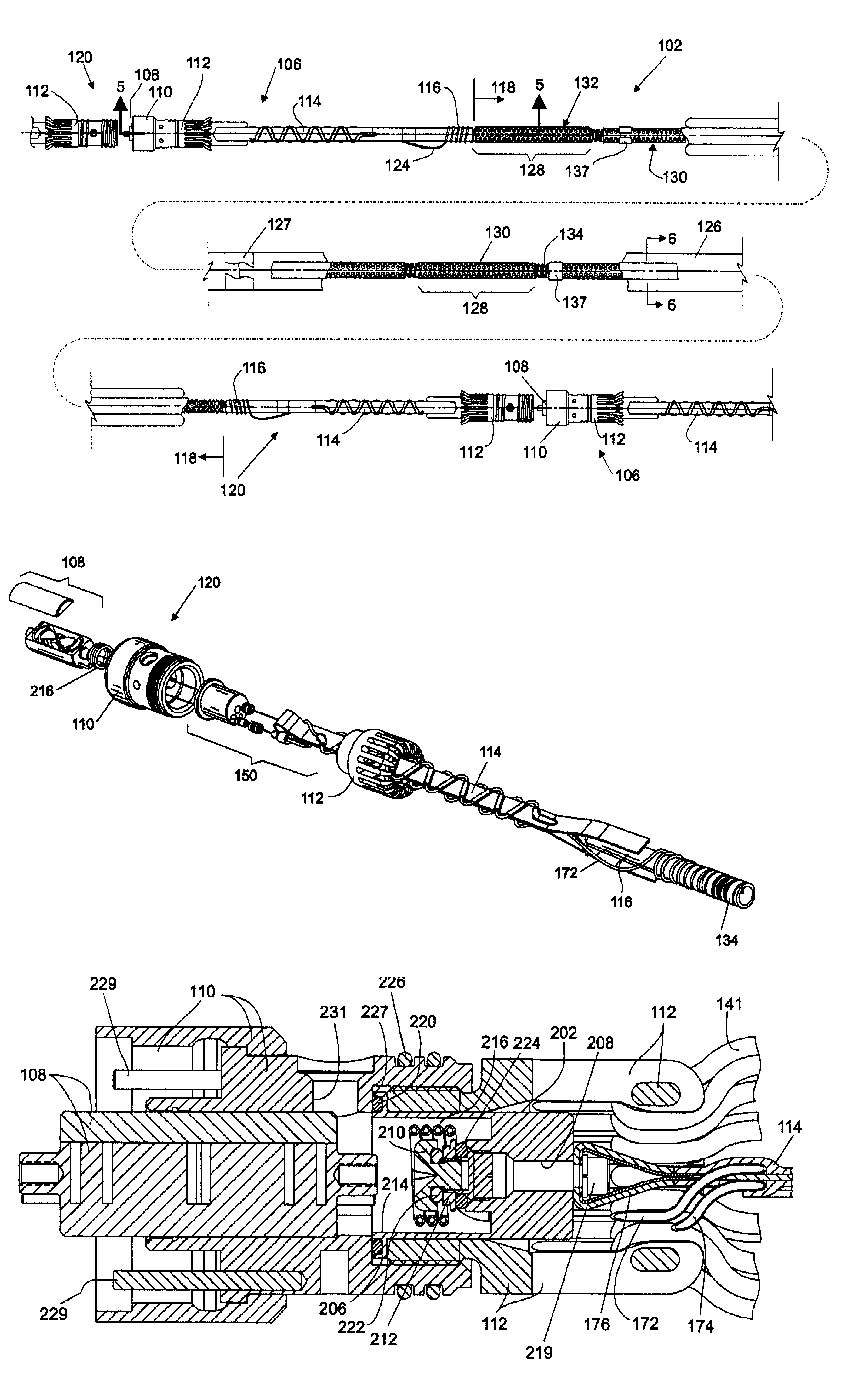
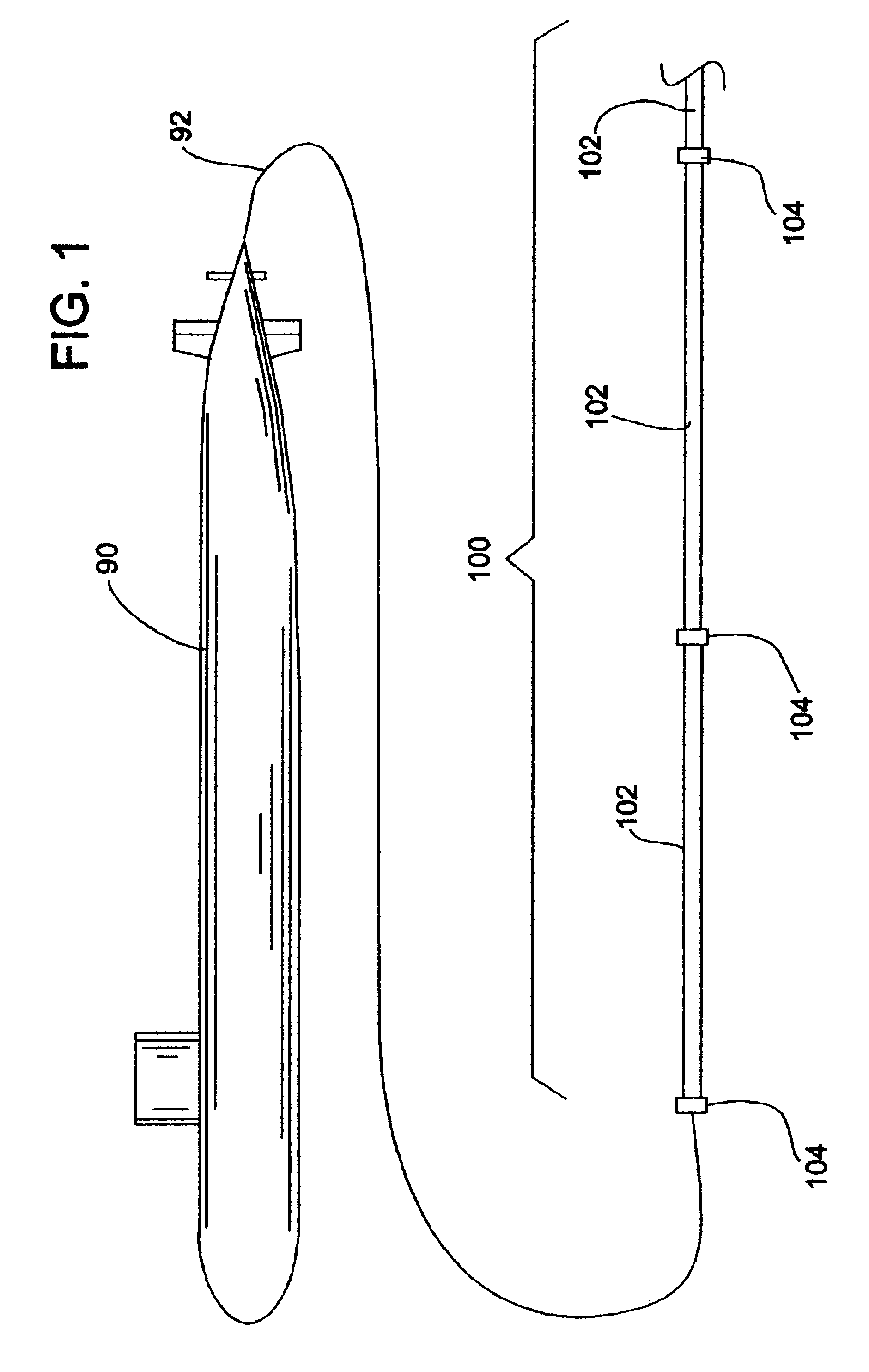
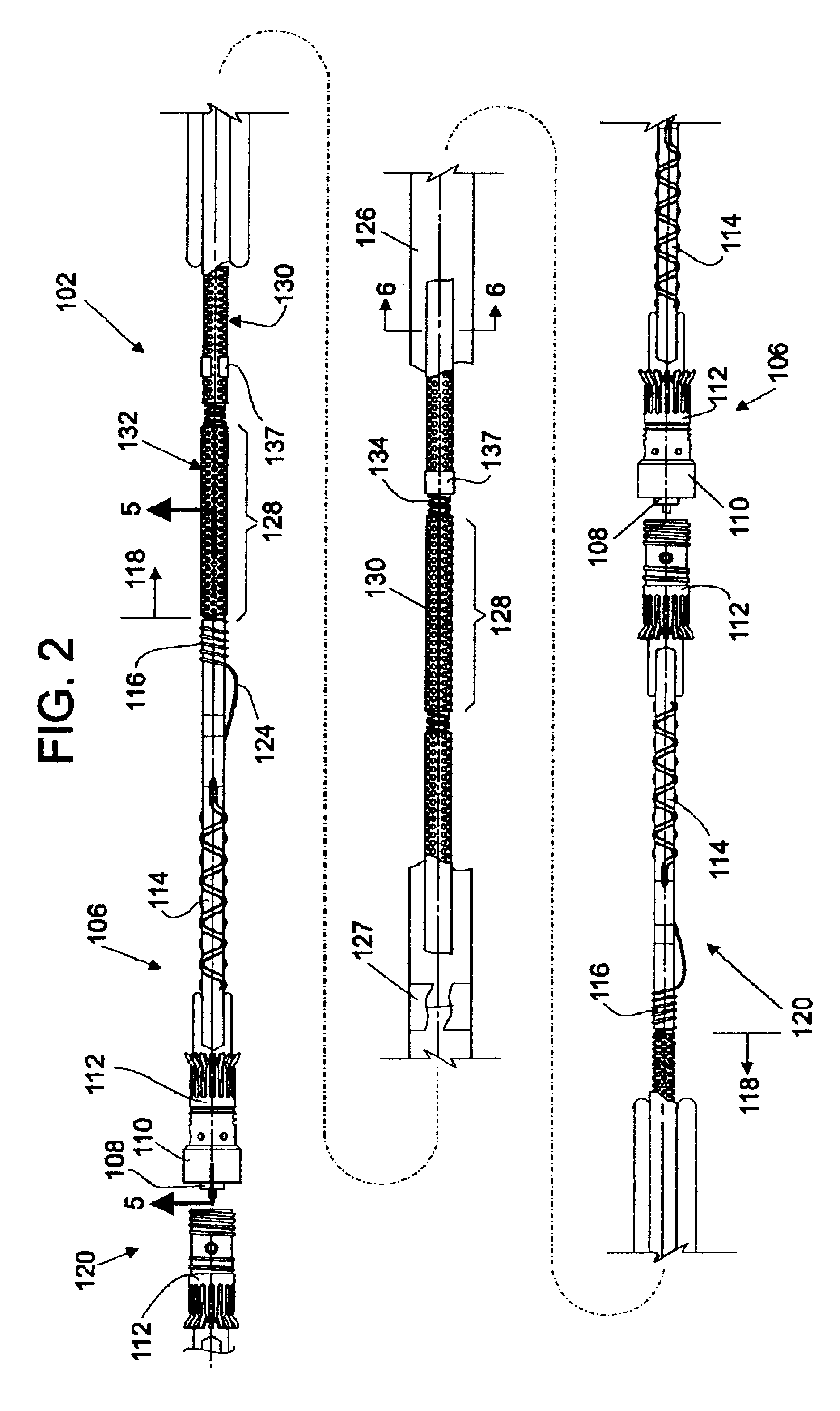
Referring now to the drawings, wherein like reference numerals illustrate corresponding or similar elements throughout the several views, there is shown in FIG. 1 a submarine 90 using a tow cable 92 to tow an optical hydrophone sonar array 100. The hydrophone array 100 is a linear array of modules 102 connected end-to-en...


PUM


Abstract

A termination assembly for use in an optical hydrophone module, comprising a module oil seal and an optical fiber seal. The termination assembly is used at the ends of modules and provides a means for filling individual modules with fill fluid. A module oil seal comprises a cylindrical wall defining a cavity, with one end substantially closed and the other end open. An annular face plate on the open end makes a seal dividing a coupling and a clevis. A check valve is mounted to an orifice that passes through the substantially closed end of the module oil seal. Optical fibers pass through the substantially closed end and the optical fiber seal is provided around the optical fiber that passes therethrough. The fiber seal fits snugly in a module oil seal opening. Both components serve to provide a seal that can withstand high pressures and maintain optical fiber integrity.

Description

BACKGROUND OF INVENTIONThe science of underwater sonar equipment is increasingly relying on the use of fiber-optic technology. This reliance is driven by the requirement to have more acoustic sensors per sonar system, with higher sensitivities and lower cost.Passive sonar arrays towed from submarines or surface ships are excellent candidates for fiber-optic sensor technology. In this area, an all optical fiber hydrophone assembly is a recent development by the United States Naval Research Laboratories. The hydrophone assembly consists of a series of air-backed plastic cylinders, called mandrels, which are helically wrapped with optical sensing fiber. The hydrophone senses sound pressure levels through the strain induced in the optical sensing fiber as the sound pressure wave deforms the mandrel. Strain is imparted in the fiber in direct proportion to the pressure induced strain in the mandrel. The characteristics of the light signal transmitted through the fiber change in relation t...

Claims


Application Information

Patent Timeline
IPC IPC(8): G02B6/44H04R1/44
CPCG02B6/4428H04R1/44
Inventor COOKE, DONALD A.MCGOVERN, KENNETH M.
Owner GENERAL DYNAMICS MISSION SYST INC
Why Eureka
Try Eureka