Train control system and method of controlling a train or trains

a technology of train control and control system, applied in the field of railroads, can solve the problems of track warrants, complicated and time-consuming procedures, and difficulty in controlling the movement of trains in a modem environment both in the train yard and on the main lin

Inactive Publication Date: 2005-03-08
SIEMENS MOBILITY INC
View PDF47 Cites 131 Cited by
  • Summary
  • Abstract
  • Description
  • Claims
  • Application Information

AI Technical Summary

Benefits of technology

In another aspect of the invention, the system can operate in a semiautomatic mode in which a conductor or engineer is able to control movement of the

Problems solved by technology

Controlling the movement of trains in a modem environment both in a train yard and on the main line is a complex process.
There is a complicated and time consuming procedure by which track warrants are issued which involves the train conductor or engineer reading back the warrant to the dispatcher before the warrant goes into effect.
One important disadvantage to this system is that it relies on human beings, both to communicate the warrant properly and to ensure that the warrant is complied with.
The system is thus subject to errors which can be disastrous.
Again, human beings are involved and errors are possible.
However, the Cab Signal system does not force the engineer/conductor to obey the more restrictive signal.
Once again, the potential for error exists.
Updated CTC systems such as the Radio Actuated Code System from Harmon Electronics integrate differential GPS (global positioning system) technology and other technology into these systems, but they are still subject to human error.
One problem with a rudimentary system such as this is that the braking operation is not started until the train passes the wayside switch, which means the train will not stop until some point after the switch.
Thus, the system will not prevent a collision with an object that is close to the wayside signal.
Another problem with all of the foregoing system is that they require wayside signaling.
These wayside signal systems are expensive to maintain and operate.
As discussed above in connection with the ABS sys

Method used


Image

  • Train control system and method of controlling a train or trains
  • Train control system and method of controlling a train or trains
  • Train control system and method of controlling a train or trains

Examples


Embodiment Construction

The present invention will be discussed with reference to preferred embodiments of train control systems. Specific details, such as specific algorithms and hardware, are set forth in order to provide a thorough understanding of the present invention. The preferred embodiments discussed herein should not be understood to limit the invention.

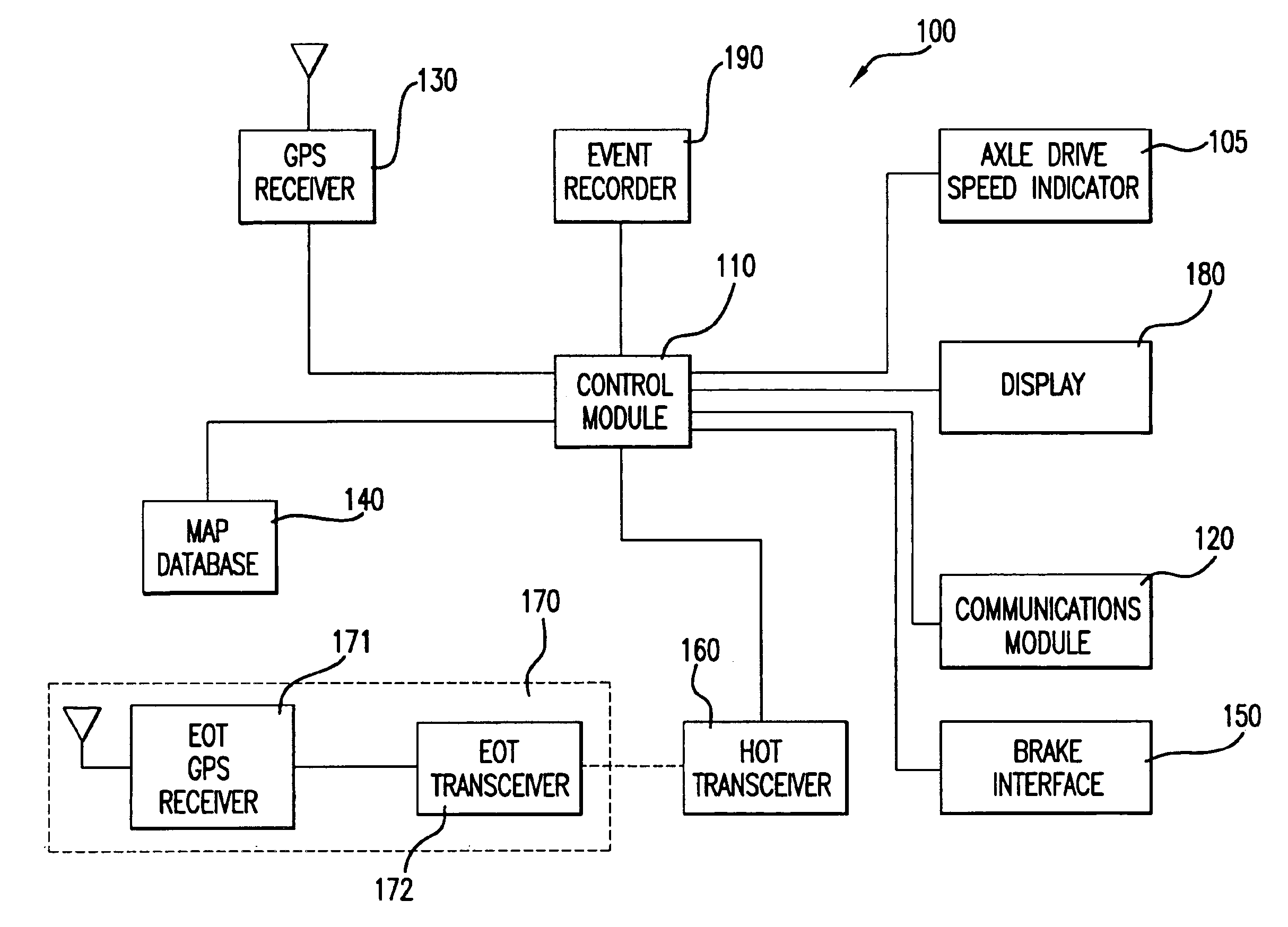
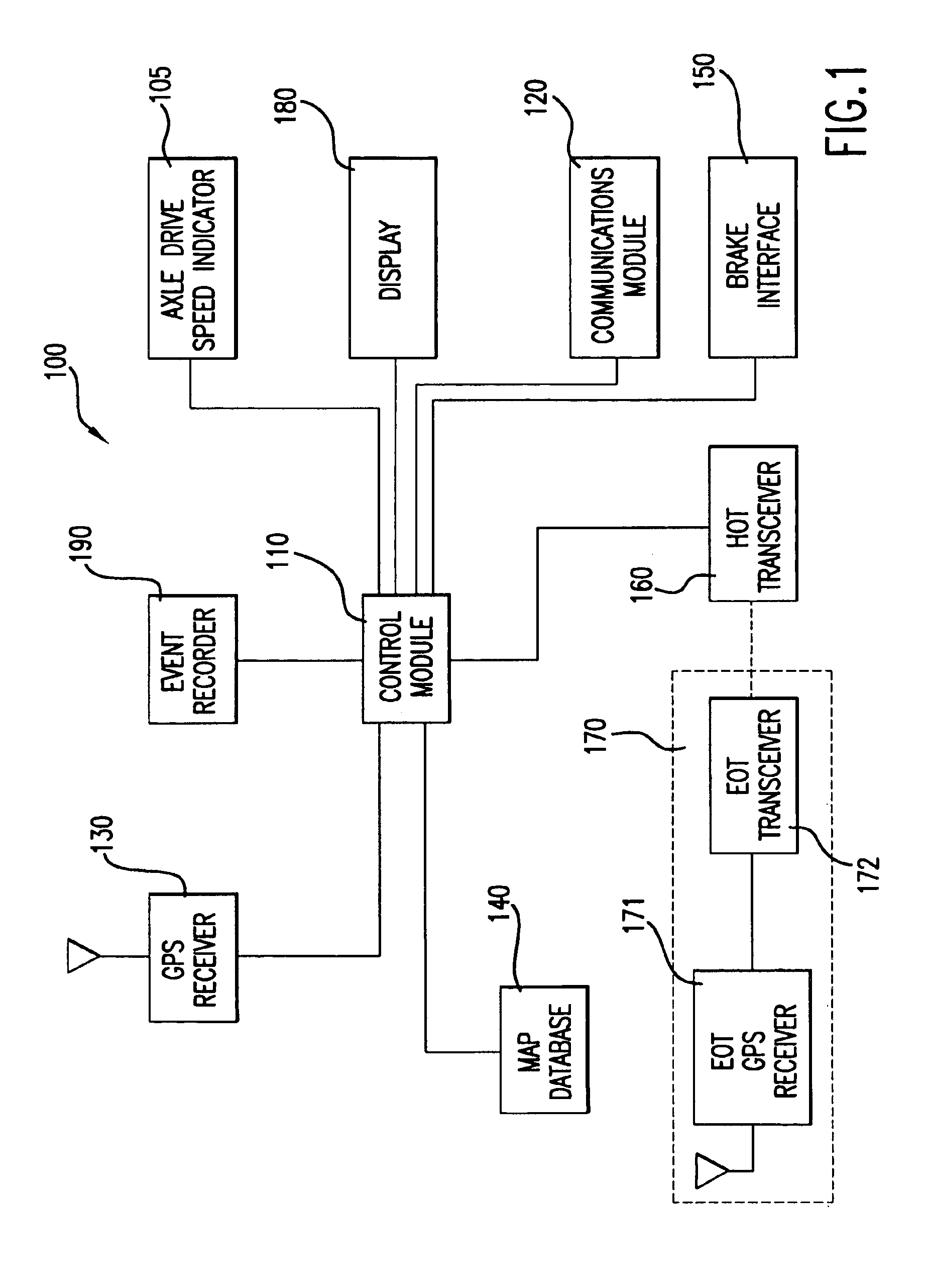
Referring now to the drawings, wherein like reference numerals designate identical or corresponding parts throughout the several views, FIG. 1 is a logical block diagram of a train control system 100 according to the present invention. The system 100 includes a control module 110, which typically, but not necessarily, includes a microprocessor. The control module 110 is the center of the train control system and is responsible for controlling the other components of the system. Connected to the control module is a communications module 120. The communications module is responsible for conducting all communications between the system 100 and the ce...


PUM


Abstract

A train control system includes positioning systems at the end of the train and at the front of the train, allowing the conductor or engineer to unambiguously determine that no cars of the train have become detached. The positioning system at the end of the train is also used to verify that the entire train has cleared a block. This information can be relayed to a dispatcher, thereby eliminating the need for trackside sensing equipment. A control unit prevents the train from moving without an authorization that includes the train's current position.

Description

BACKGROUND OF THE INVENTION1. Field of the InventionThe invention relates to railroads generally, and more particularly to automatic control of trains.2. Discussion of the BackgroundControlling the movement of trains in a modem environment both in a train yard and on the main line is a complex process. Collisions with other trains must be avoided and regulations in areas such as grade crossings must be complied with. The pressure to increase the performance of rail systems, in terms of speed, reliability and safety, has led to many proposals to automate various aspects of train operation.One traditional method for controlling trains is known as track warrant control. This method is most often used in areas of dark territory (track that does not include a wayside signaling system). Simply put, a track warrant is permission to occupy a given section of track, i.e., a block. The traditional track warrant control method, which is defined in the General Code of Operational Rules, involve...

Claims


Application Information

Patent Timeline
IPC IPC(8): B61L15/00
CPCB61L3/008B61L15/0027B61L15/0036B61L15/0054B61L15/0072B61L15/0081B61L25/021B61L25/023B61L25/025B61L25/026B61L27/0038B61L15/009B61L2205/04B61L27/20
Inventor KANE, MARK EDWARDSHOCKLEY, JAMES FRANCISHICKENLOOPER, HARRISON THOMAS
Owner SIEMENS MOBILITY INC
Why Eureka
Try Eureka