Method and apparatus at a spinning preparation machine for cleaning fiber material

Inactive Publication Date: 2005-03-15
TRUETZSCHLER GMBH & CO KG
View PDF17 Cites 5 Cited by
  • Summary
  • Abstract
  • Description
  • Claims
  • Application Information

AI Technical Summary

Benefits of technology

It is an aim of the invention to provide a method of the type described at the beginning that avoids or mitigates

Problems solved by technology

This also means, however, that, in the event of an incorrect adjustment, an excessive amount of good material is generally removed or else the available cleaning potential is not fully utilised.
That problem arises especially when there are frequent changes of materials being proc

Method used


Image

  • Method and apparatus at a spinning preparation machine for cleaning fiber material
  • Method and apparatus at a spinning preparation machine for cleaning fiber material
  • Method and apparatus at a spinning preparation machine for cleaning fiber material

Examples


Embodiment Construction

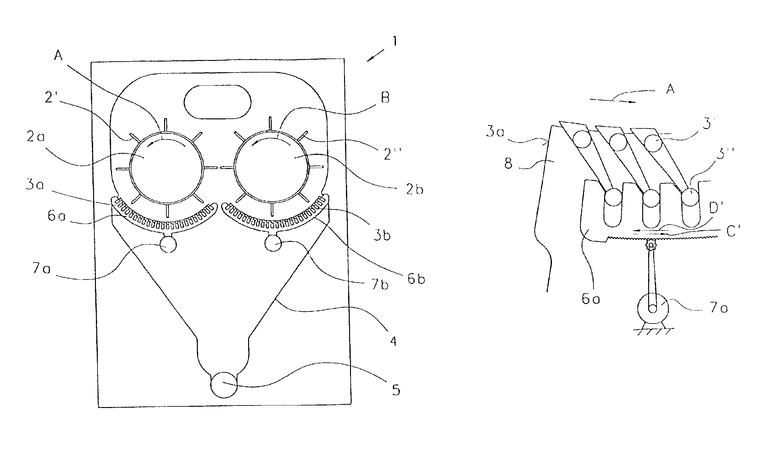
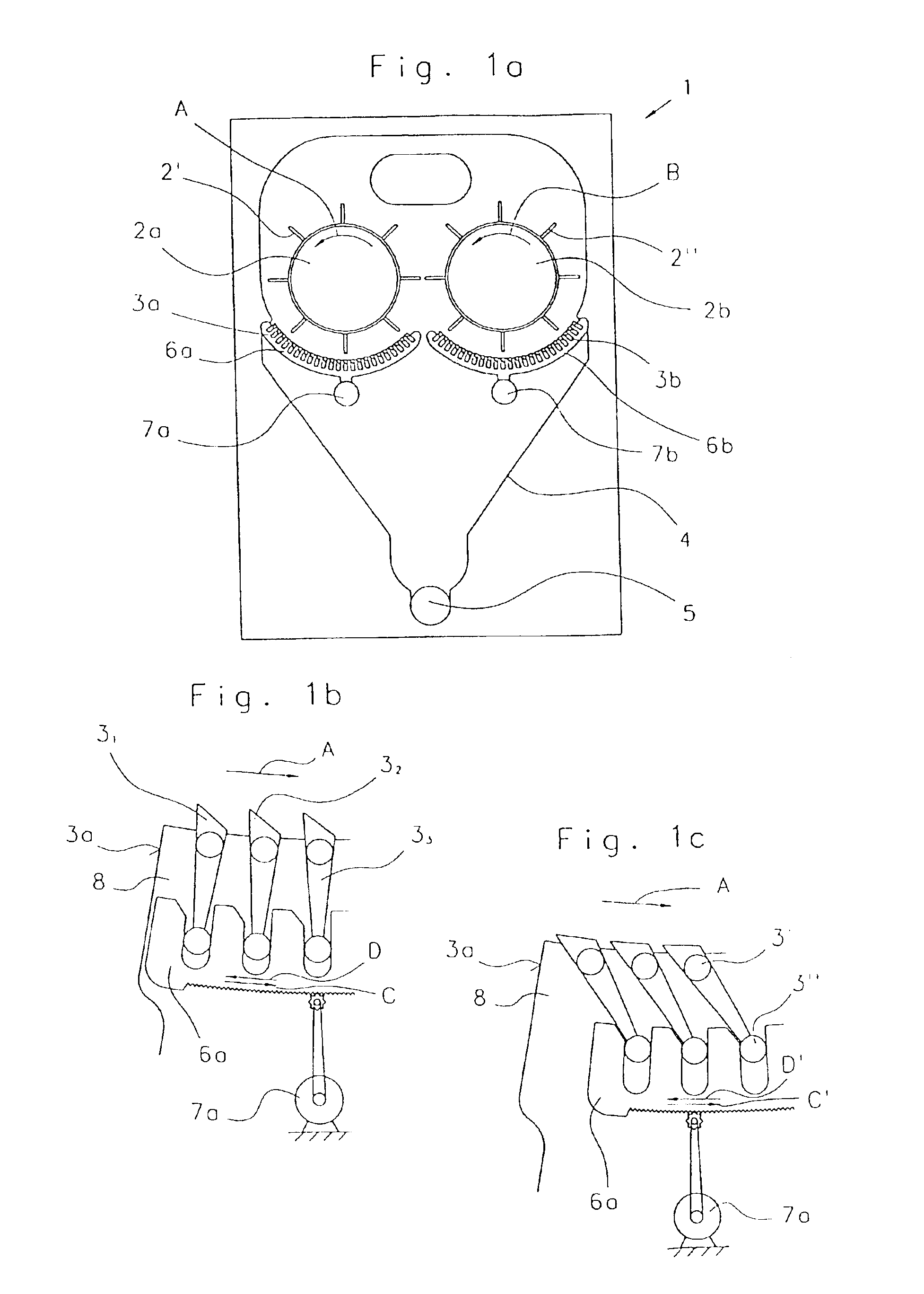
Referring to FIG. 1a, a double-roller cleaning machine 1 (axial cleaner), for example a MAXI-FLO MFC cleaner made by Trutzschler GmbH & Co of Mönchengladbach, Germany, has two rotating opener rollers 2a, 2b, underneath which there are arranged grids 3a, 3b having through-holes. The opener rollers 2a, 2b rotate anti-clockwise, in accordance with arrows A, B. The supply of the fibre material to be cleaned and the removal of the cleaned fibre material is analogous to that shown diagrammatically in FIGS. 5 and 6. Underneath the grids 3a, 3b there is a trash-collecting unit 4, which has a pneumatic trash-removing line 5. Fixed to the circumference of the opener rollers 2a, 2b are beater spikes 2′, 2″, which pass the supplied fibre flocks over the cleaning bars 31 to 3n of the cleaning grids 3a, 3b, which are arranged around part of the circumference of the opener rollers 2a, 2b. The position of the grid bars 31 to 3n (cleaning bars) is adjustable (see FIGS. 1b, 1c) so that, as a result, ...


PUM


Abstract

In a method at a spinning preparation machine, for example a cleaner, opener, carding machine or the like, for cleaning fiber material, especially cotton, an examination of the nature of the trash is carried out, which examination is used for adjustment of at least one adjustable cleaning element, for example a separating blade, cleaning grid or the like.
In order to make possible improved and undisrupted production by simple means, the optimum adjustment of the at least one cleaning element for a specific fiber batch is stored in a memory of an electronic control and regulation device and, when the same fiber batch is processed again, the optimum adjustment of the cleaning element is implemented automatically.

Description

CROSS REFERENCE TO RELATED APPLICATIONThis application claims priority from German Patent Application No. 102 30 603.6 which is incorporated herein by reference.BACKGROUND OF THE INVENTIONThe invention relates to a method at a spinning preparation machine, for example a cleaner, opener, carding machine or the like, for cleaning fibre material, especially cotton and further encompasses an apparatus for carrying out the method.In a known arrangement, an examination of the nature of the trash is carried out, which examination is used for adjustment of at least one adjustable cleaning element, for example a separating blade, cleaning grid or the like.In practice, in textile cleaning machines, especially—for example—in a pre-cleaner, the degree of cleaning is adjusted substantially with the aid of grids that can be regulated manually. This means that the amount and nature of trash material removed is dependent upon the grid positions. This also means, however, that, in the event of an in...

Claims


Application Information

Patent Timeline
IPC IPC(8): D01G15/00D01G15/34
CPCD01G15/34
Inventor HOSEL, FRITZ
Owner TRUETZSCHLER GMBH & CO KG
Why Eureka
Try Eureka