Utility device having an improved rotatable drive mechanism
What is Al technical title?
Al technical title is built by PatSnap Al team. It summarizes the technical point description of the patent document.
a technology of rotatable drive mechanism and utility device, which is applied in the direction of tractors, thinning machines, spades, etc., can solve the problems of a variety of limitations of existing devices
Inactive Publication Date: 2005-03-15
UNVERFERTH MFG
View PDF4 Cites 10 Cited by
Summary
Abstract
Description
Claims
Application Information
AI Technical Summary
This helps you quickly interpret patents by identifying the three key elements:
Problems solved by technology
Method used
Benefits of technology
Benefits of technology
The preferred embodiments of the present invention can significantly improve upon existing systems and methods. In some preferred embodiments, a utility vehicle is provided that has an improved rotated drive mechanism.
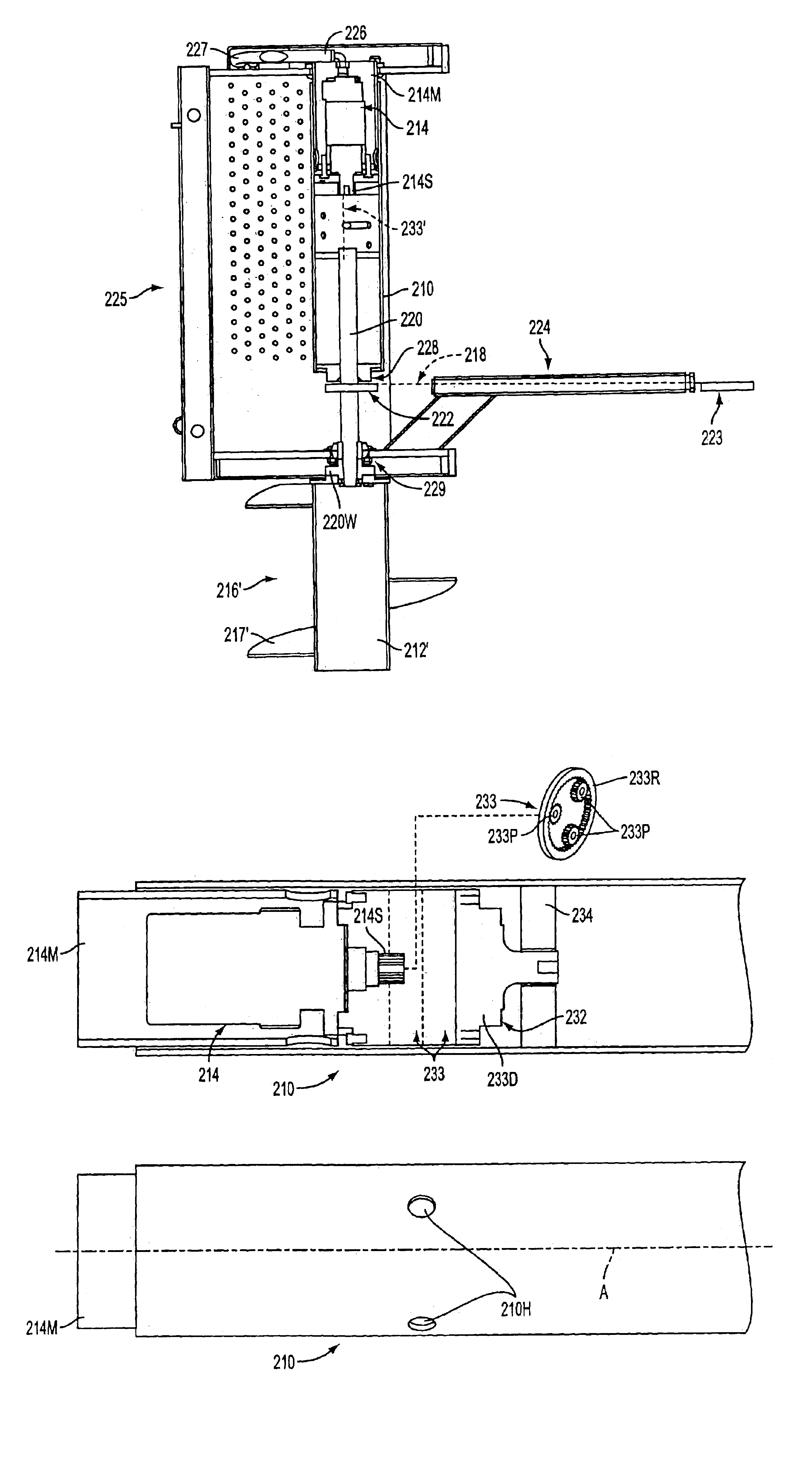
In some embodiments, a soil-engaging utility device having a utility mechanism with a motor-driven utility drum is provided that includes: a support to support the device on a vehicle; a utility mechanism including a rotatable drum, the drum including at least one soil-engaging member on a periphery of the drum, the drum being positionable generally horizontally and generally transverse to the vehicle; a motor contained substantially entirely inside the drum, the motor having a drive shaft extending inwards into the drum; planetary gear set inside the drum and operatively connected to the drive shaft to increase torque between the drive shaft and the drum, the planetary gear set converting a higher revolution-per-minute rotation to a lower revolution-per-minute rotation; and an output of the planetary gear set being operatively connected to the drum at a connection location that is displaced inward from ends of the drum to reduce torsion on the drum.
In some embodiments, a soil-engaging utility device having a utility mechanism with a motor-driven utility drum is provided that includes: a support to support the device on a vehicle; the utility mechanism including a rotatable drum, the drum including at least one soil-engaging member extending around a periphery of the drum, the drum being positionable generally horizontally and generally transverse to the vehicle; a motor contained substantially entirely inside the drum, the motor having a drive shaft extending inwards into the drum; the drive shaft being operatively connected to the drum at a connection location that is displaced inward from ends of the drum to reduce torsion on the drum; the drive shaft also being operatively connected to a second utility mechanism so as to effect movement of the second utility mechanism.
Problems solved by technology
Nevertheless, existing devices have a variety of limitations.
Method used
Image
Click on the blue label to locate the original text in one second.
Reading with bidirectional positioning of images and text.
Examples
Embodiment Construction
The preferred embodiments of the present invention can significantly improve upon existing systems and methods. In some preferred embodiments, a utility vehicle is provided that has an improved rotated drive mechanism.
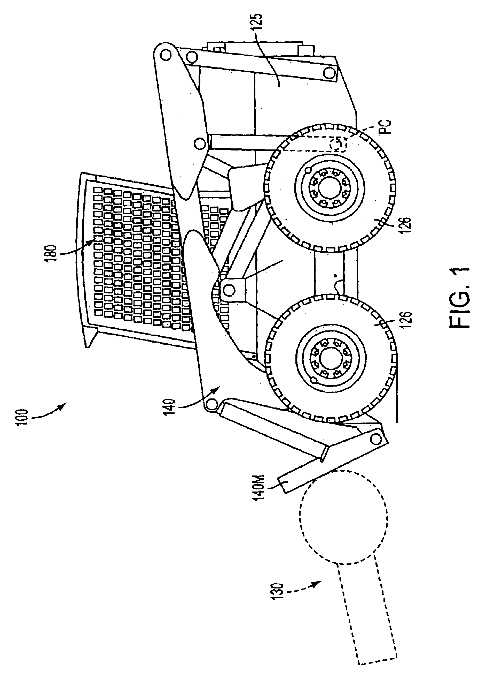
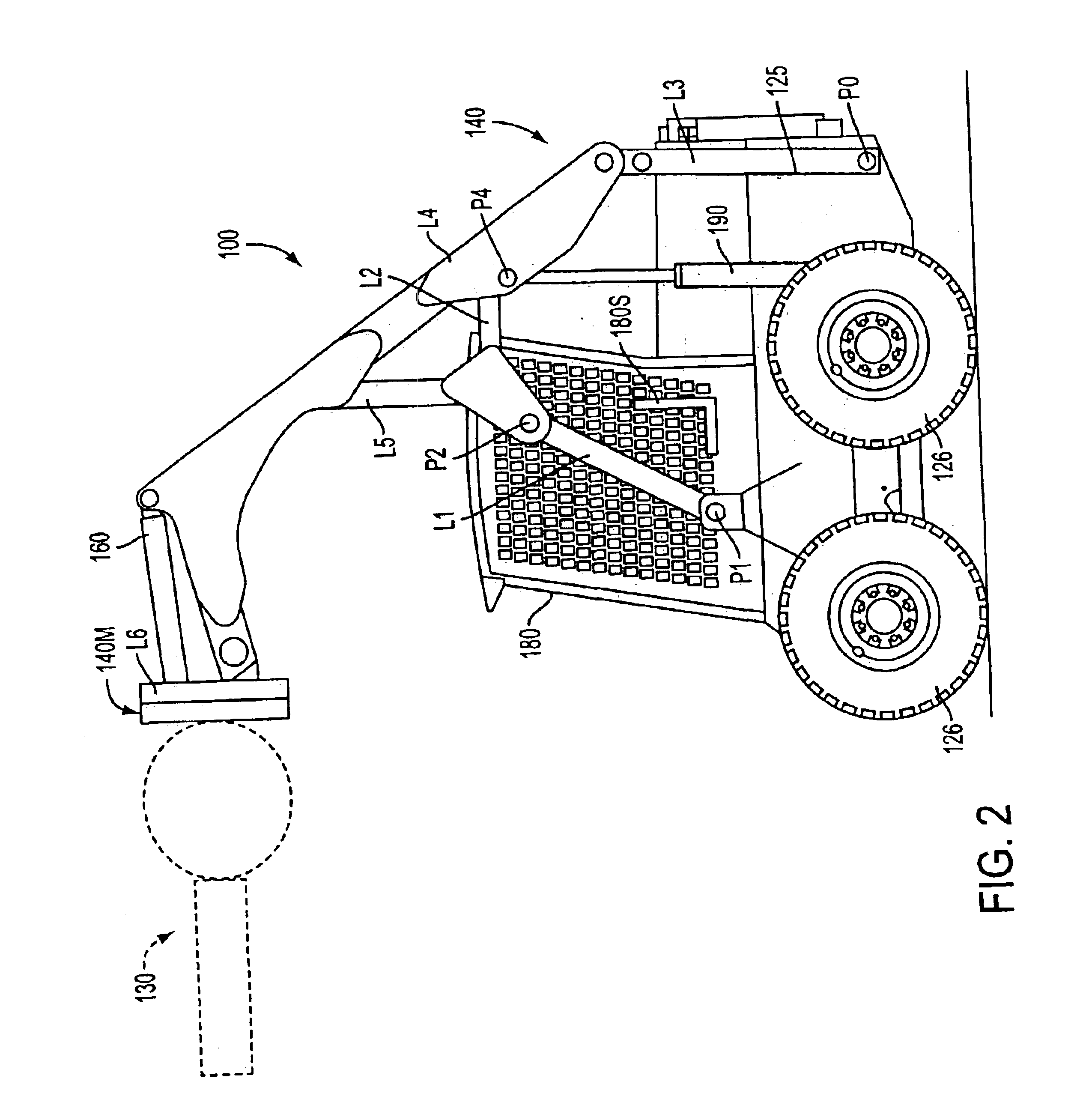
In some embodiments, a utility vehicle or other device for excavating soil or the like includes a utility mechanism, such as, e.g., a trencher, an auger or the like, with a motor-driven utility drum. In preferred embodiments, the motor is contained substantially entirely inside the drum. Preferably, the drive shaft is operatively connected to the drum to rotate the drum at a connection location that is displaced inward from ends of the drum. In some embodiments, the drive shaft is also preferably operatively connected to a second utility mechanism, such as, e.g., a trencher chain. In some embodiments, a planetary transmission is also located inside the drum.
In some embodiments, a soil-engaging utility device having a utility mechanism with a motor-driven utility drum i...
PUM
Abstract
A utility vehicle or other device for excavating soil or the like includes a utility mechanism, such as, e.g., a trencher, an auger or the like, with a motor-driven utility drum. In preferred embodiments, the motor is contained substantially entirely inside the drum. Preferably, the drive shaft is operatively connected to the drum to rotate the drum at a connection location that is displaced inward from ends of the drum. In some embodiments, the drive shaft is also preferably operatively connected to a second utility mechanism, such as, e.g., a trencher chain. In some embodiments, a planetary transmission is also located inside the drum.
Description
BACKGROUND1. Field of the InventionThe present invention relates generally to, among other things, utility devices, such as, for example, utility vehicles, having utility mechanisms, such as, for example, trenchers and / or the like with rotated drive mechanisms.2. Discussion of the BackgroundThere are a variety of known utility vehicles having utility mechanisms with rotated drive mechanisms. In many instances, utility vehicles are often used for construction and / or other utilitarian purposes, such as, e.g., for lifting, pushing, scraping, digging, plowing and / or various other purposes. In many instances, the vehicles include a) a main body having at least one seat for a vehicle operator (such as, for example, a seat located within a protective cab), b) wheels and / or other supports mounted on the body portion for supporting the same, and c) a utility mechanism mounted to the vehicle (such as, e.g., via a utility boom). In some illustrative cases, the utility mechanism(s) can include,...
Claims
Application Information
Patent Timeline
Application Date:The date an application was filed.
Publication Date:The date a patent or application was officially published.
First Publication Date:The earliest publication date of a patent with the same application number.
Issue Date:Publication date of the patent grant document.
PCT Entry Date:The Entry date of PCT National Phase.
Estimated Expiry Date:The statutory expiry date of a patent right according to the Patent Law, and it is the longest term of protection that the patent right can achieve without the termination of the patent right due to other reasons(Term extension factor has been taken into account ).
Invalid Date:Actual expiry date is based on effective date or publication date of legal transaction data of invalid patent.
