
Tube compressing roller die

Inactive Publication Date: 2005-03-15
WALDROP WESLEY TODD
View PDF15 Cites 4 Cited by
  • Summary
  • Abstract
  • Description
  • Claims
  • Application Information

AI Technical Summary

Benefits of technology

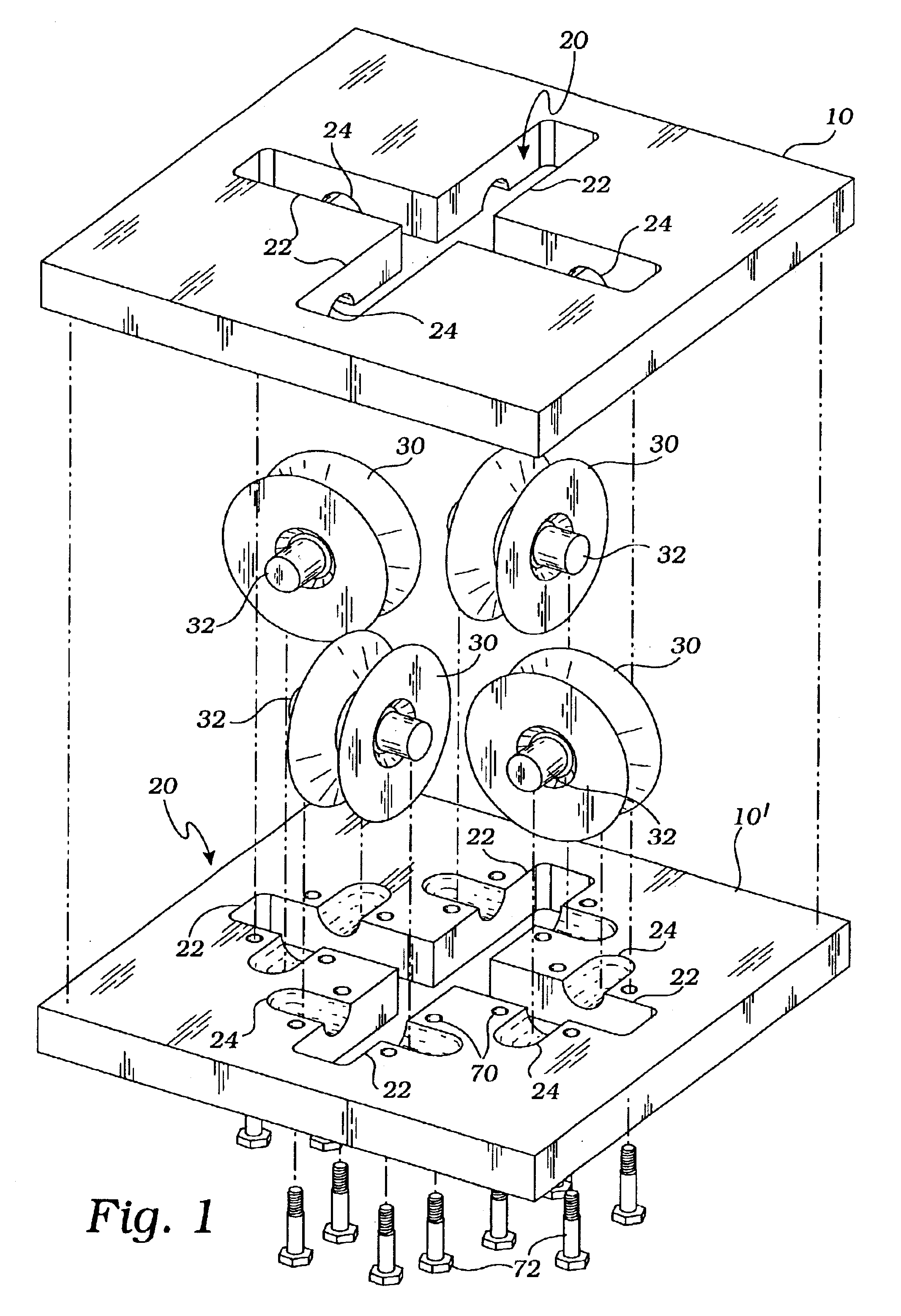
A tube reduction die uses a pair of plates, each of the plates providing an X-shaped aperture therein. The X-shaped aperture comprises two pairs of opposing slots, and each slot provides a pair of opposing grooves. The grooves are oriented at right angles to the slots. The pair of plates are in face to face contact with the X-shaped apertures, grooves and slots aligned. A set of four wheels are mounted on transverse axles which are captured in the grooves with the wheels positioned in the slots and rotating on bearings. A V-shaped concave annular face has a semi-circular annular notch at its apex. The four wheels are positioned such that their edges are in mutual adjacency forming a square passage between them. A tube is forced into the square passage and is uniformly reduced in size while maintaining its square shape and without excessive sidewall deformation.
A still further objective is to provide such an invention capable of reducing the tube in size without causing excessive side wall deformation.

Problems solved by technology

The prior art teaches apparatus for reducing the diagonal dimensions of a rectangular billet, rolling mills with diametrically opposed rollers for reshaping the corners of a tube or billet, a method for depressing portions of a cylindrical tube, a machine adapted for forming a groove along the length of a pipe, and designs for rolling mills and buffing machines, but does not teach a simplified apparatus and method for reducing the size of an end of a sheet metal tube.

Method used


Image

  • Tube compressing roller die
  • Tube compressing roller die
  • Tube compressing roller die

Examples


Embodiment Construction

The above described drawing figures illustrate the invention in at least one of its preferred embodiments, which is further defined in detail in the following description.

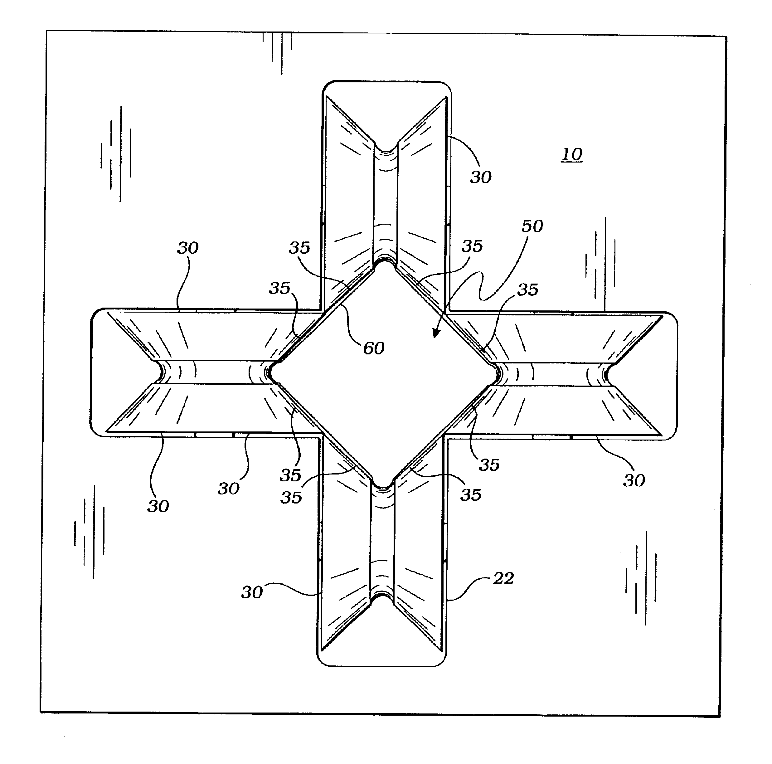
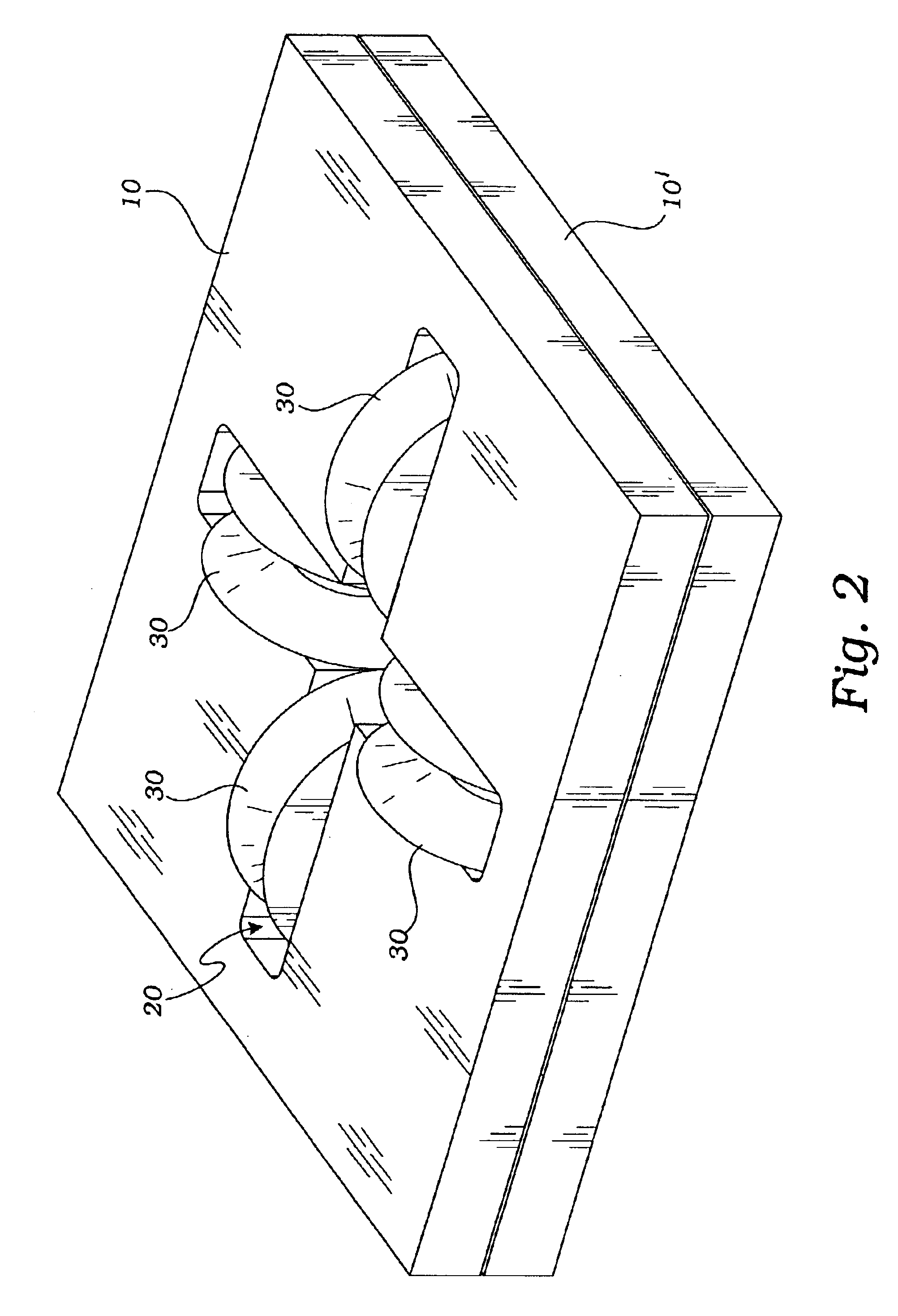
The present invention is a tube reduction apparatus. A pair of plates 10, 10′ are preferably made of steel or similar structural material and are both pierced with an X-shaped aperture 20 as shown in FIGS. 1 and 2. The X-shaped apertures 20 each comprise two pairs of opposing slots 22, with each of the slots 22 providing a pair of opposing grooves 24 oriented at right angles to the slots 22. This is clearly shown in the lower plate of FIG. 1. The pair of plates 10, 10′ are in face-to-face contact with the X-shaped apertures 20, the opposing slots 22 and the grooves 24 aligned and the grooves 24 abutting, as shown in FIG. 1. A set of four wheels 30 each mounted on a transverse axles 32. An annular face 34 of each of the wheels 30 provides a concave V-shape. An apex 36 of the annular face 34 provides a semi-circular ...


PUM

PropertyMeasurementUnit
Angleaaaaaaaaaa

Abstract

A tube reduction apparatus uses a pair of plates, each of the plates providing an X-shaped aperture therein. The X-shaped aperture comprises two pairs of opposing slots, and each slot provides a pair of opposing grooves. The grooves are oriented at right angles to the slots. The pair of plates are in face to face contact with the X-shaped apertures, grooves and slots aligned. A set of four wheels are mounted on transverse axles which are captured in the grooves with the wheels positioned in the slots. A V-shaped concave annular face has an has a semi-circular annular notch at its apex. The four wheels are positioned such that their edges are in mutual adjacency forming a square passage therebetween them.

Description

BACKGROUND OF THE INVENTIONINCORPORATION BY REFERENCE: Applicant(s) hereby incorporate herein by reference, any and all U.S. patents, U.S. patent applications, and other documents and printed matter cited or referred to in this application.1. Field of the InventionThis invention relates generally to tube working dies and more particularly to a roller die for compressing or reducing the size of a square or rectangular tube and especially for compressing one end of a square tube for adapting the end for being inserted into a non-reduced tube end of the same size tubing.2. Description of Related ArtThe following art defines the present state of this field:Omerza, U.S. Des. No. 397,601 describes a design buffer for buffing round articles.Schrepfer, U.S. Des. No. 400,895 describes a design for a roller mill.Elting, U.S. Pat. No. 1,890,077 describes the art of constructing sheet metal tubing comprising kneading parts of the material of a sheet to be formed into tubing while preserving the...

Claims


Application Information

Patent Timeline
IPC IPC(8): B21C3/00B21C3/08B21D41/00B21D41/04
CPCB21D41/04B21C3/08
Inventor WALDROP, WESLEY TODD
Owner WALDROP WESLEY TODD
Learn More