Sequential rotated feeding circuit

a feeding circuit and sequential rotation technology, applied in the direction of electrical equipment, multiple-port networks, waveguides, etc., can solve the problems of deteriorating signal transmission effect, increasing distance between, and complex design of conventional so as to simplify the line width design of sequential rotation feeding circuits, reduce dimensions, and allow more design freedom

Inactive Publication Date: 2012-08-14
NAT TAIWAN UNIV
View PDF4 Cites 0 Cited by
  • Summary
  • Abstract
  • Description
  • Claims
  • Application Information

AI Technical Summary

Benefits of technology

[0012]The embodiment of the invention simplifies the line width design thereof, and allows more design freedom. A circuit area of the sequential rotated feeding circuit may be reduced, and the shape of the sequential rotated feeding circuit may be a square. Compared with conventional art, the embodiment of the invention has decreased dimensions, a reduced side lobe and improved signal transmission effect.

Problems solved by technology

The large dimensions of the conventional sequential rotated feeding circuit causes increased distances between antenna units of the antenna array, which generates a side lobe, and deteriorates signal transmission effect.
Thus, the design of conventional sequential rotated feeding circuit is complex, with large circuit area.

Method used


Image

  • Sequential rotated feeding circuit
  • Sequential rotated feeding circuit
  • Sequential rotated feeding circuit

Examples


first embodiment

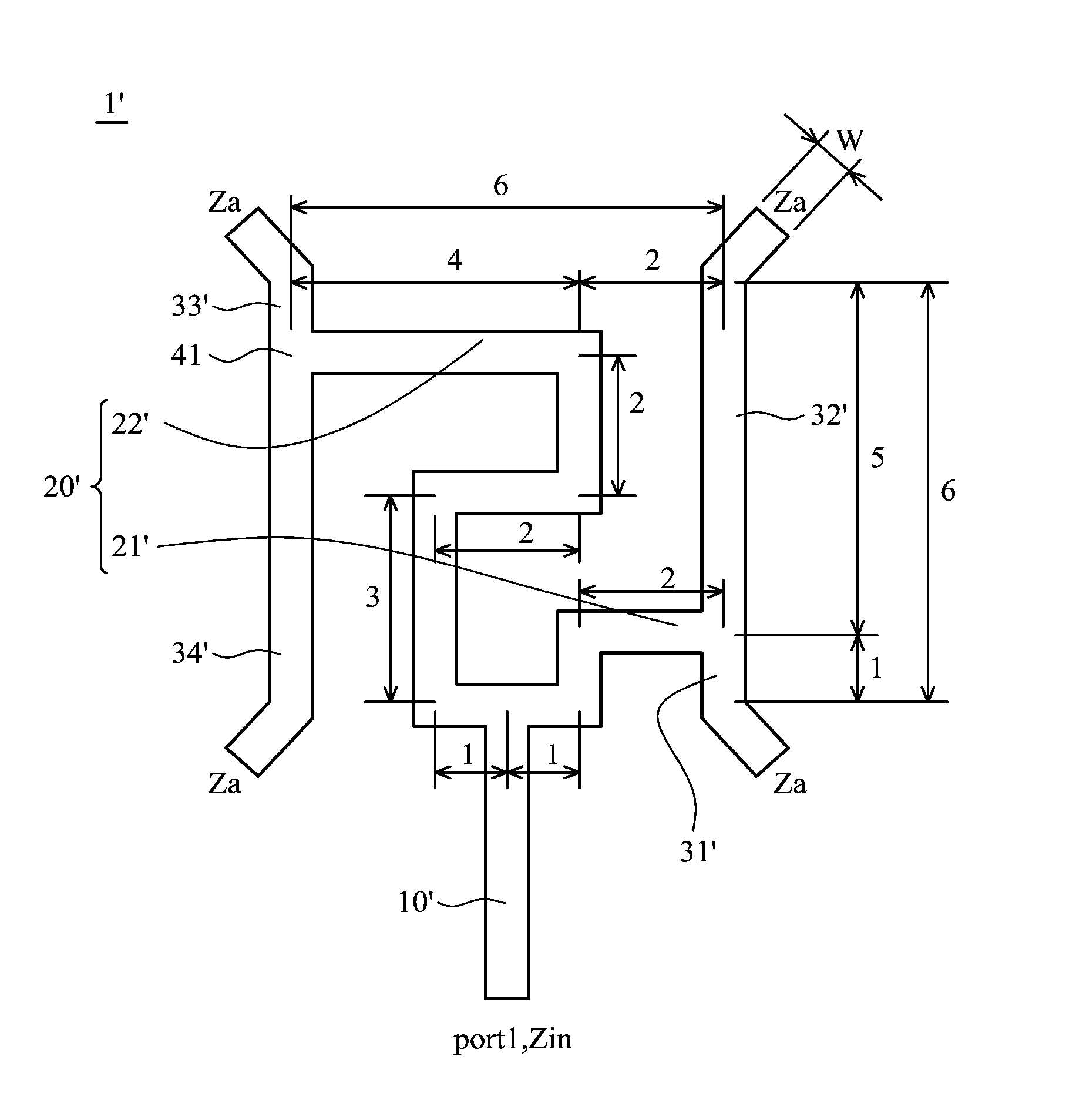
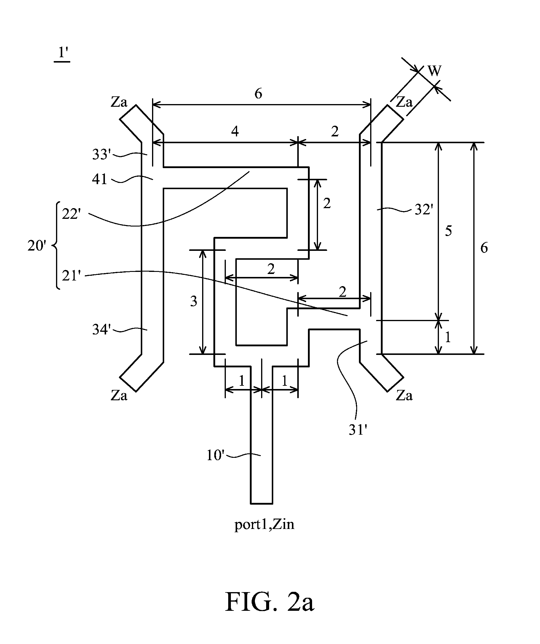
[0032]FIG. 2a shows a sequential rotated feeding circuit 1′ of the invention. The sequential rotated feeding circuit 1′ comprises a feed transformer 10′, a resistance transforming unit 20′, a first antenna transformer 31′, a second antenna transformer 32′, a third antenna transformer 33′ and a fourth antenna transformer 34′. The resistance transforming unit 20′ comprises a first resistance transformer 21′ and a second resistance transformer 22′. The first resistance transformer 21′ and the second resistance transformer 22′ are connected to the feed transformer 10′. The first antenna transformer 31′ is connected to the first resistance transformer 21′. The second antenna transformer 32′ is connected to the first resistance transformer 21′. The third antenna transformer 33′ is connected to the second resistance transformer 22′. The fourth antenna transformer 34′ is connected to the second resistance transformer 22′.

[0033]The first resistance transformer comprises a first resistance tr...

second embodiment

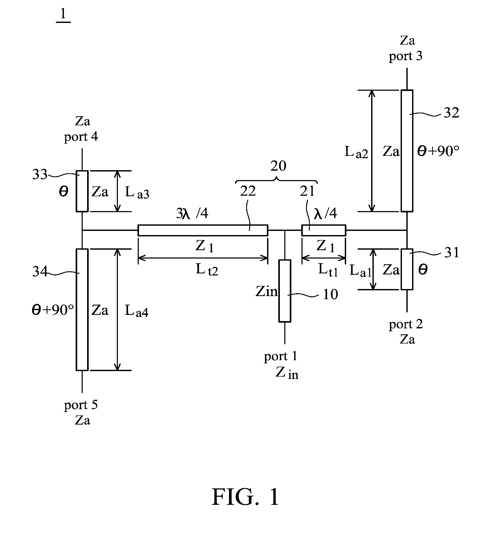
[0044]FIG. 3a shows a sequential rotated feeding circuit 1″ of the invention. The sequential rotated feeding circuit 1″ comprises a feed transformer 10″, a resistance transforming unit 20″, a second antenna transformer 32″, and a fourth antenna transformer 34″. The resistance transforming unit 20″ comprises a first resistance transformer 21″ and a second resistance transformer 22″. The first resistance transformer 21″ and the second resistance transformer 22″ are connected to the feed transformer 10″. The second antenna transformer 32″ is connected to the first resistance transformer 21″. The fourth antenna transformer 34″ is connected to the second resistance transformer 22″.

[0045]The first resistance transformer comprises a first resistance transforming length Lt1″ the second resistance transformer comprises a second resistance transforming length Lt2″, the first resistance transforming length Lt1″ is

[0046]λg4,

and the second resistance transforming length Lt2″ is

[0047]3⁢λg4.

[0048]...


PUM


Abstract

A sequential rotated feeding circuit for sequential rotated feeding of a signal with a wavelength λg is provided. The sequential rotated feeding circuit comprises a feed transformer, a resistance transforming unit, a first antenna transformer, a second antenna transformer, a third antenna transformer and a fourth antenna transformer. The feed transformer has a feed line width resistance Zin. The resistance transforming unit is connected to the feed transformer, the first antenna transformer, the second antenna transformer, the third antenna transformer and the fourth antenna transformer. The resistance transforming unit has a transforming line width resistance Zl. The first antenna transformer, the second antenna transformer, the third antenna transformer and the fourth antenna transformer have an antenna line width resistance Za, and the feed line width resistance Zin, the transforming line width resistance Zl, and the antenna line width resistance Za satisfy the following formula:Zl=√{square root over (ZaZin)}.

Description

CROSS REFERENCE TO RELATED APPLICATIONS[0001]This Application claims priority of Taiwan Patent Application No. 098122372, filed on Jul. 2, 2009, the entirety of which is incorporated by reference herein.BACKGROUND OF THE INVENTION[0002]1. Field of the Invention[0003]The present invention relates to a sequential rotated feeding circuit, and in particular relates to a sequential rotated feeding circuit with decreased dimensions.[0004]2. Description of the Related Art[0005]Sequential rotated feeding circuits are utilized for feeding signals to an antenna array. There are three types of conventional sequential rotated feeding circuits: (a) Parallel type, (b) Series type, and (c) Hybrid ring with parallel type. A conventional sequential rotated feeding circuit is relatively large. For example, a parallel type sequential rotated feeding circuit has a circuit area about[0006]3⁢λ4×3⁢λ4,wherein λ is a wavelength of a wireless signal transmitted by the antenna array. A series type sequential ...

Claims


Application Information

Patent Timeline
Patent Type & Authority Patents(United States)
IPC IPC(8): H01P5/12
CPCH01P5/12
Inventor LIN, SHIH-KAILIN, YI-CHENG
Owner NAT TAIWAN UNIV
Why Eureka
Try Eureka