Eureka AIR delivers breakthrough ideas for toughest innovation challenges, trusted by R&D personnel around the world.

Gasket for fuel injector

a fuel injector and gasket technology, applied in the field of gaskets, can solve the problems of high temperature and high pressure, and achieve the effects of reducing clamping force, reducing noise, vibration, and effective sealing against leakag

Inactive Publication Date: 2005-03-15
FEDERAL MOGUL WORLD WIDE LLC
View PDF17 Cites 34 Cited by
  • Summary
  • Abstract
  • Description
  • Claims
  • Application Information

AI Technical Summary

Benefits of technology

The gasket provides an effective seal against leakage of combustion gases and isolates the injector from direct contact with the cylinder head to limit the transmission of noise, vibration, and the like, between the cylinder head and injector. The gasket allows lower clamping forces on the injector to diminish the transmission of such noise, vibration, and the like.

Problems solved by technology

The combustion chamber of the cylinder into which the fuel injector supplies fuel creates high temperatures and high pressures that are subjected to the interface between the injector and the bore of the cylinder head in which it is disposed.
However, this high clamping load facilitates the transmission of vibration and noise from the injector.

Method used


Image

  • Gasket for fuel injector
  • Gasket for fuel injector
  • Gasket for fuel injector

Examples


Embodiment Construction

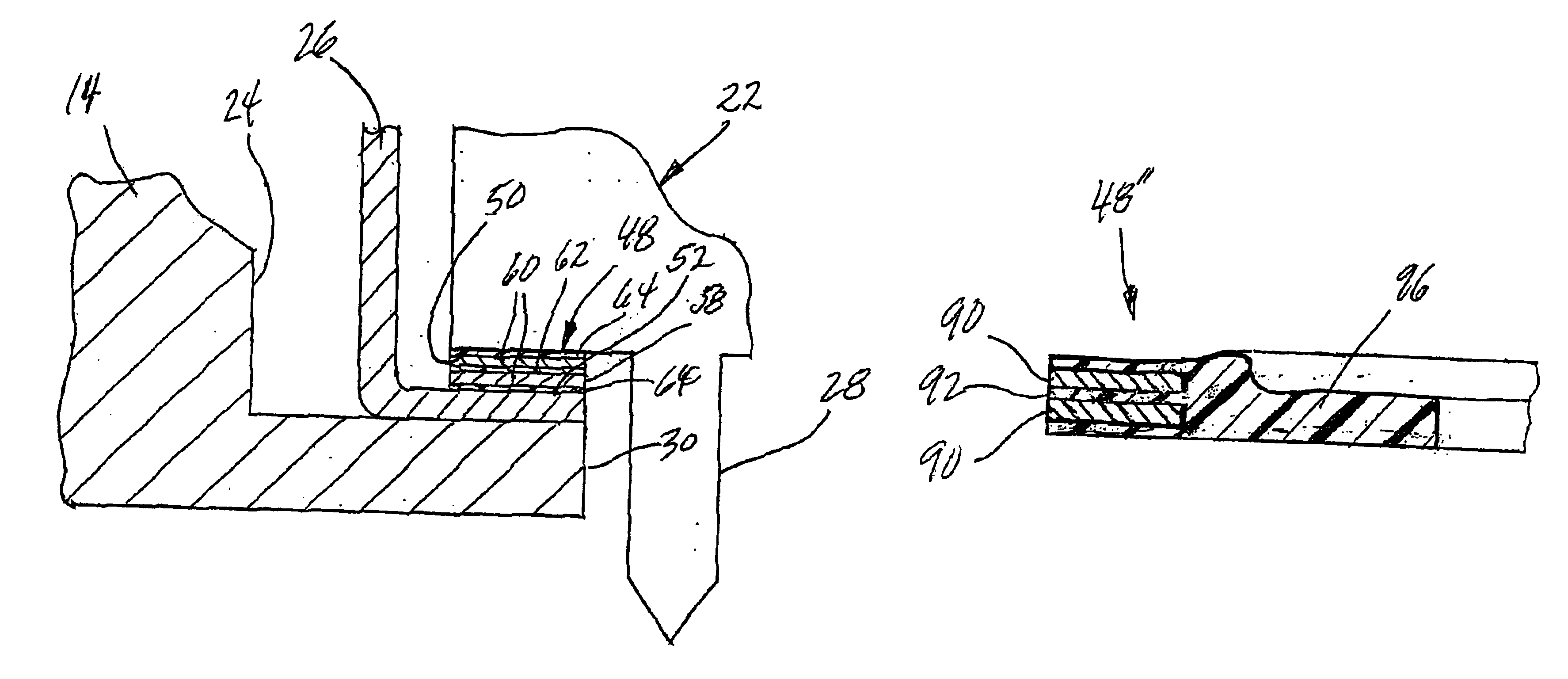
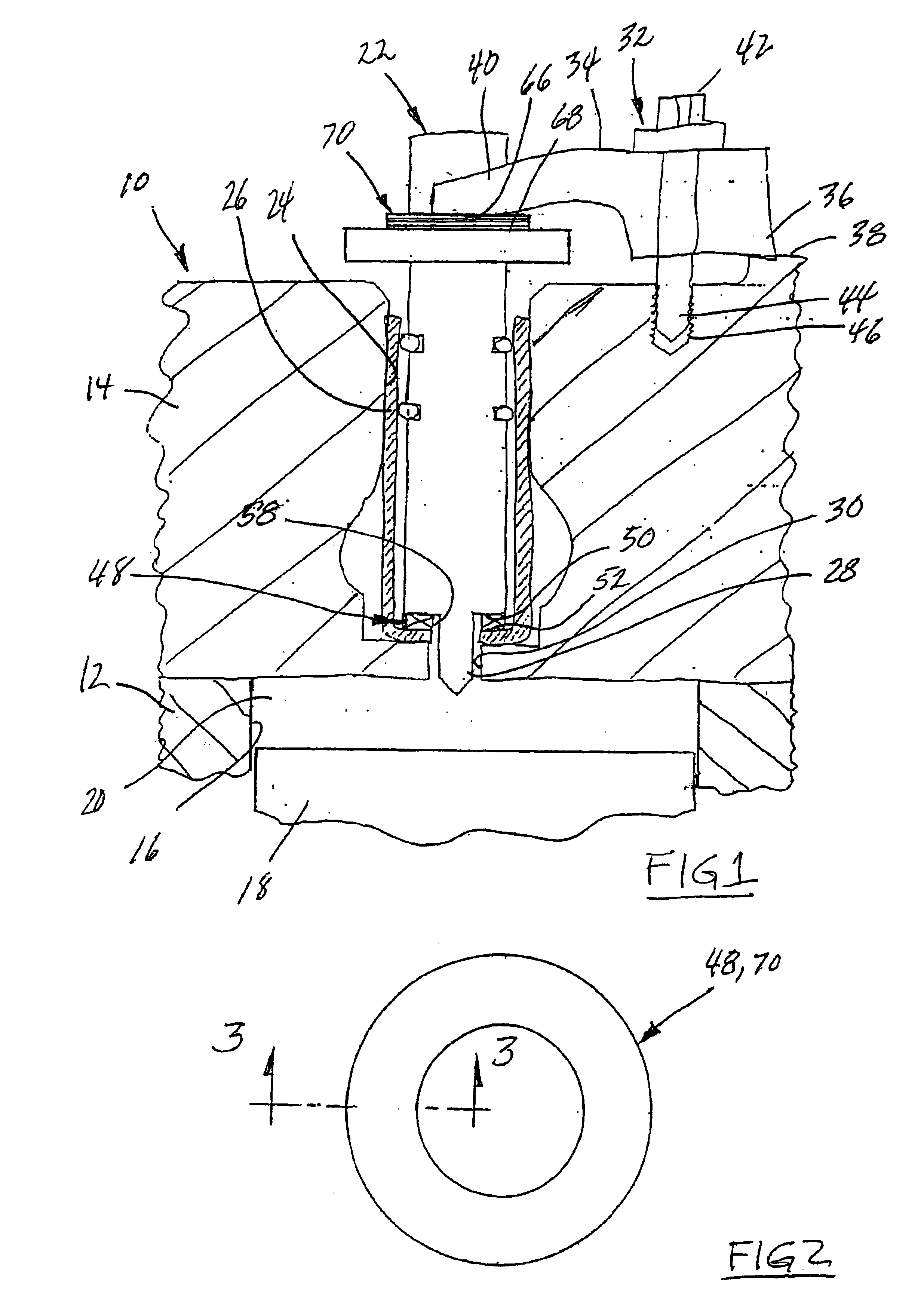
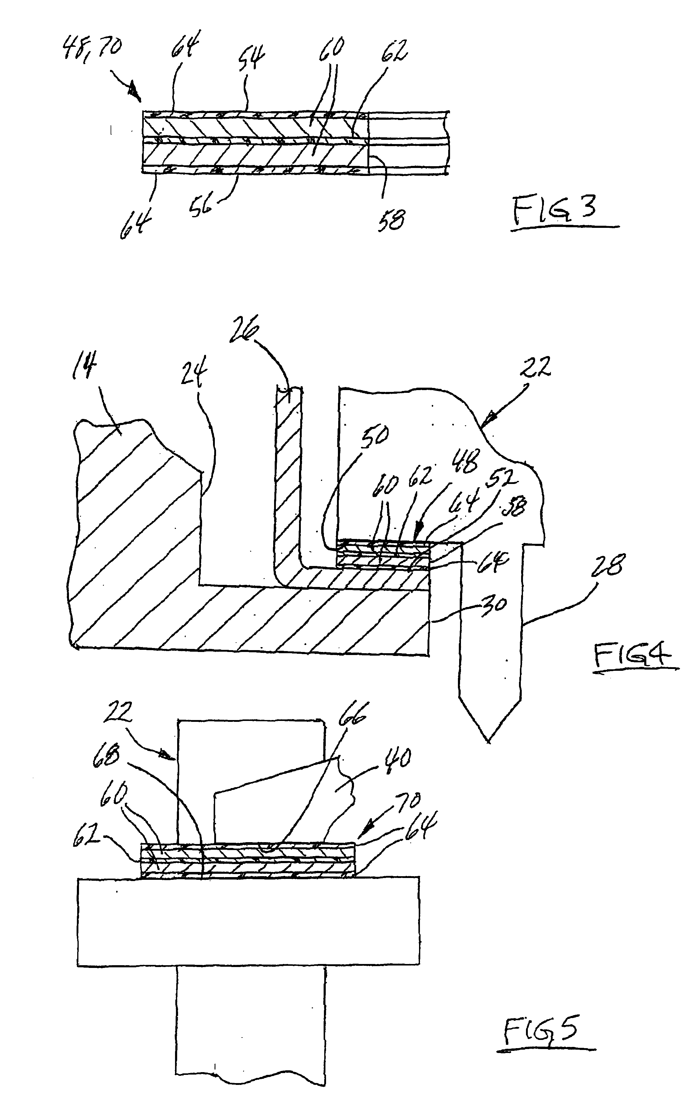
Referring to the Figures, wherein like numerals indicate like or corresponding parts throughout the several views, an internal combustion engine is generally shown at 10, and particularly a diesel engine, having an engine block 12, a cylinder head 14, and a piston cylinder 16 accommodating a reciprocating piston 18 and defining a combustion chamber 20 between the piston 18 and head 14 confined by the walls of the cylinder 16 in known manner.

A fuel injector 22 is disposed in an injector bore 24 of the head 14 and a sleeve 26 lines the bore 24. An injector tip or nozzle 28 extends through an opening 30 in the head 14 and the sleeve 26 leading to the combustion chamber 20 for delivery of fuel by the injector 20 in known manner. The injector 22 is fixed in place by an injector clamp 32. The clamp 32 comprises a clamp arm 34 resting at an outer end 36 on a support surface 38 of the head 14 and extends in cantilevered fashion therefrom to a forked end 40 in position over the injector 22, ...


PUM


Abstract

A gasket (48, 48′, 48″) and (70) for disposition between a fuel injector (22) and a cylinder head (14) comprises compressible polymer layers (62, 64, 74, 92) and incompressible and flat metal layers (60, 72, 90) sandwiched between the polymer layers. In the embodiments of FIGS. 6-8, a polymer body (80, 96) is disposed radially inwardly of the incompressible layer (72) or layers (90) and includes a bead portion (86) thicker than the total thickness of the incompressible and polymer layers (72), and (74, 90) and (92). The body (80, 96) also includes a recess portion (82-84) having a thickness less than the total thickness to define a recess (88) adjacent the bead portion (86). The bead portion (86) is disposed radially between the recess portion (82-84) and the incompressible layer (72 or 90).

Description

BACKGROUND OF THE INVENTION1. Field of the InventionThe subject invention relates to a gasket particularly suitable for disposition between a cylinder head and a fuel injector in an internal combustion engine.2. Description of the Related ArtThe prior art is replete with gaskets for disposition between a fuel injector and the bore of a cylinder head in an internal combustion engine. The combustion chamber of the cylinder into which the fuel injector supplies fuel creates high temperatures and high pressures that are subjected to the interface between the injector and the bore of the cylinder head in which it is disposed. Various configurations of gaskets are used to seal this gap and examples are disclosed in U.S. Pat. No. 3,038,456 to Dresin, U.S. Pat. No. 5,785,024 to Takei et al and U.S. Pat. No. 6,334,433 to Sumida et al.In order to obtain the desired sealing characteristics, it has been the practice to apply a relatively high clamping force on the injector to urge the injector ...

Claims


Application Information

Patent Timeline
Patent Type & Authority Patents(United States)
IPC IPC(8): F02M61/00F02M61/14F16J15/12
CPCF02M61/14F16J15/122F02M2200/858F02M2200/09
Inventor MICKELSON, MICHAEL
Owner FEDERAL MOGUL WORLD WIDE LLC
Why Eureka
Eureka Blog
Learn More