Fuel tank vent system with liquid fuel filter

a technology of liquid fuel filter and fuel tank, which is applied in mechanical equipment, transportation and packaging, functional valve types, etc., can solve the problem of not being able to discharge excessive amounts of liquid fuel into the vapor recovery canister

Inactive Publication Date: 2005-03-15
STANT USA CORP
View PDF29 Cites 28 Cited by
  • Summary
  • Abstract
  • Description
  • Claims
  • Application Information

AI Technical Summary

Benefits of technology

According to the present disclosure, a fuel tank vent apparatus is provided. The fuel tank vent apparatus is configured to vent fuel vapor from a fuel tank while minimizing the amou...

Problems solved by technology

However, it is not desirable to discharge excessive...

Method used


Image

  • Fuel tank vent system with liquid fuel filter
  • Fuel tank vent system with liquid fuel filter
  • Fuel tank vent system with liquid fuel filter

Examples


Embodiment Construction

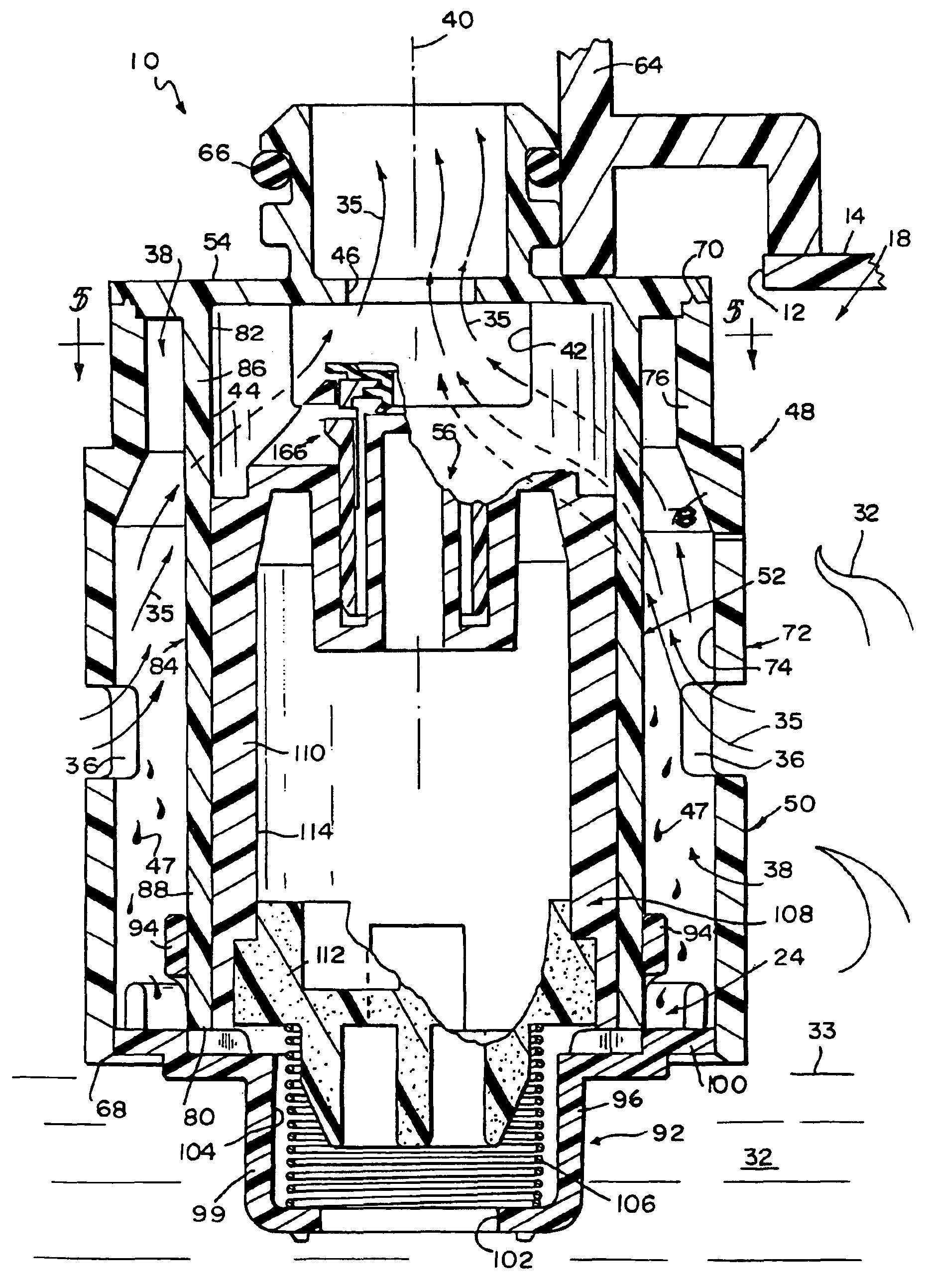
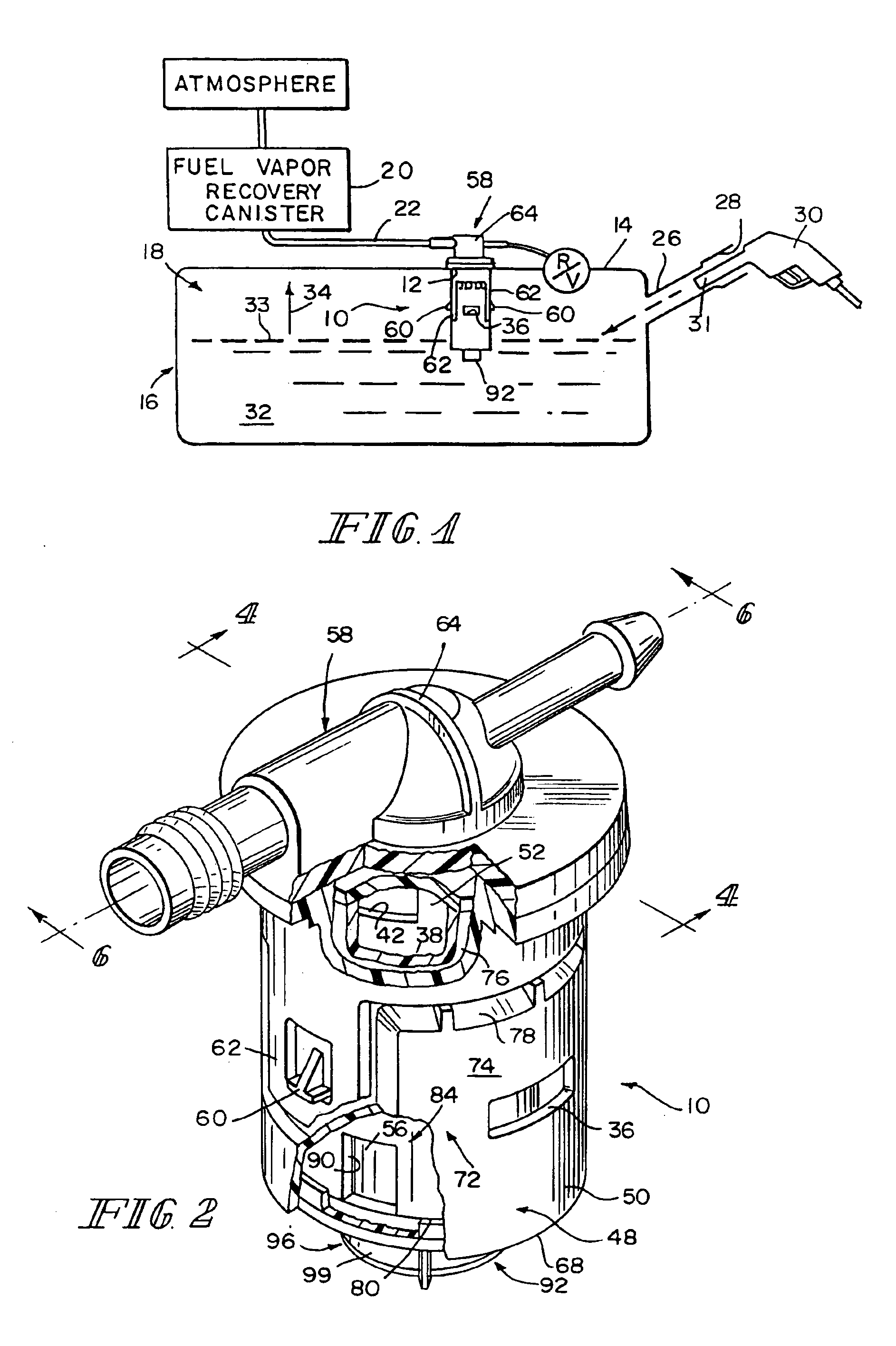
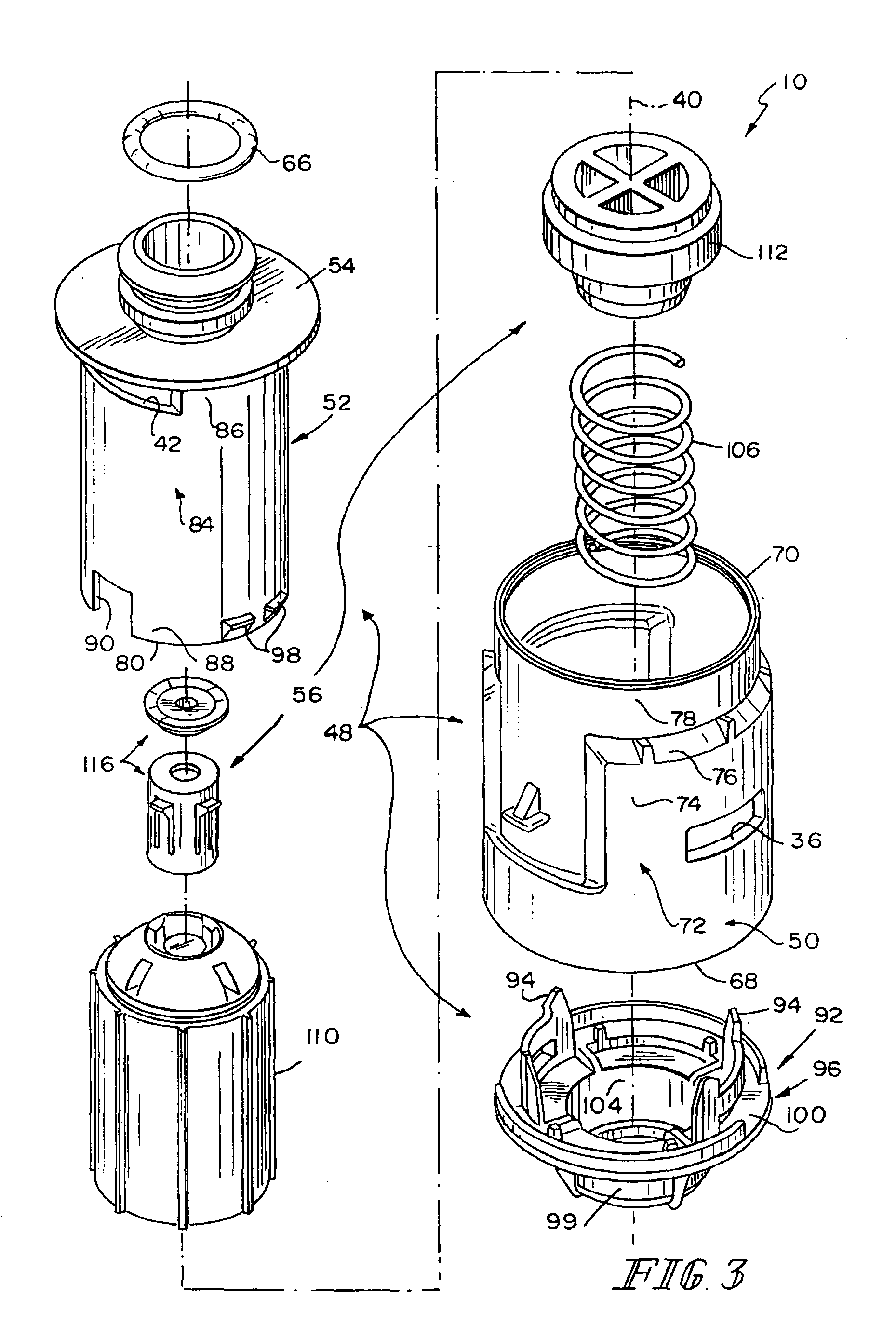
A fuel tank vent apparatus 10 is mounted in an aperture 12 formed in a top wall 14 of a fuel tank 16 to regulate flow of pressurized fuel vapor from a vapor space 18 provided in tank 16 to a fuel vapor recovery canister 20 through a discharge conduit 22, as shown, for example, in FIG. 1. Vent apparatus 10 is configured to cause fuel vapor traveling therethrough to shed liquid fuel entrained therein and to collect such liquid fuel in a liquid fuel accumulation chamber 24 shown in FIGS. 4 and 6 and formed in a lower portion of vent apparatus 10. Thus, vent apparatus 10 acts as a liquid fuel carryover filter to prevent excessive amounts of liquid fuel from exiting tank 16 through discharge conduit 22 and then reaching the fuel vapor recovery canister 20 coupled to discharge conduit 22.

A filler neck 26 is coupled to fuel tank 16 and formed to include an inlet 28 sized to receive a fuel-dispensing pump nozzle 30 as shown, for example, in FIG. 1. Nozzle 30 is used by a pump operator to in...


PUM


Abstract

A fuel tank vent apparatus comprises a housing. The housing comprises inner and outer sleeves providing a fuel vapor transfer passageway therebetween so that liquid fuel entrained in fuel vapor is shed therefrom as fuel vapor flows from a fuel vapor transfer port formed in the outer sleeve through the fuel vapor transfer passageway to a fuel vapor inlet port formed in the inner sleeve to produce a flow of demoisturized fuel vapor for discharge from the housing.

Description

BACKGROUNDThe present disclosure relates to fuel tank valve apparatus, and particularly to a liquid fuel filter for use with a fuel vapor vent system in a fuel tank. More particularly, the present disclosure relates to a system for venting fuel vapor from a tank to a vapor recovery canister without excessive carryover of liquid fuel from the tank to the canister.Vehicle fuel systems include tank-mounted valves for venting pressurized or displaced fuel vapor from the vapor space in a fuel tank to a vapor recovery canister located outside of the fuel tank. The canister is designed to capture and store fuel entrained in fuel vapors that are displaced and generated in the fuel tank during a typical vehicle refueling operation or that are otherwise vented from the fuel tank.However, it is not desirable to discharge excessive amounts of liquid fuel into the vapor recovery canister. This is especially true during “maneuvering” of fuel tank vapor control apparatus mounted on a moving fuel t...

Claims


Application Information

Patent Timeline
IPC IPC(8): B60K15/035B60K15/03F16K24/04F16K24/00
CPCB60K15/03519F16K24/044B60K15/03504B60K2015/03514B60K2015/03509Y10T137/0874Y10T137/3099Y10T137/7771Y10T137/86324
Inventor BROCK, MICHAEL S.GROOM, J BRADLEY
Owner STANT USA CORP
Why Eureka
Try Eureka