Cable connector assembly with latching means

a technology of cable connectors and latching means, which is applied in the direction of contact members penetrating/cutting insulation/cable strands, coupling device connections, electrical apparatus, etc., can solve the problems of deformation of insulation displacement portions, adversely affecting power transmission between them, and no support for insulation displacement portions, etc., to achieve more reliable signal or power transmission

Inactive Publication Date: 2005-03-15
HON HAI PRECISION IND CO LTD
View PDF9 Cites 17 Cited by
  • Summary
  • Abstract
  • Description
  • Claims
  • Application Information

AI Technical Summary

Benefits of technology

An object of the present invention is to provide a cable connector assembly for achieving a more reliable signal or power transmission.

Problems solved by technology

Therefore, once there is one wire not electrically connected with a corresponding contact reliably, the power transmission therebetween is adversely affected.
That is, the insulation displacement portions have no support when a flat cable is urged thereto.
This may cause a deformation of the insulation displacement portions and an unreliable signal transmission between the cable and the contacts.
However, the inner walls may partly block an operator's line of sight on inserting of the wires into the dual slots.
Therefore, the accuracy of the insertion of the wires is not assured.
However, this complexes the structure of the contact and increases the manufacturing cost thereof.
However, the cover structure is mainly used for a flat cable, not for a single wire, and the assembly is relatively complex in structure.
However, the protrusions are very tiny in figure, and walls of the cover are relatively thin.
Thus, the engagement between the cover and the housing is not secure, the wires still has a possibility of inadvertently separating from the insulation displacement portions of the contacts and the power transmission is adversely influenced.

Method used


Image

  • Cable connector assembly with latching means
  • Cable connector assembly with latching means
  • Cable connector assembly with latching means

Examples


Embodiment Construction

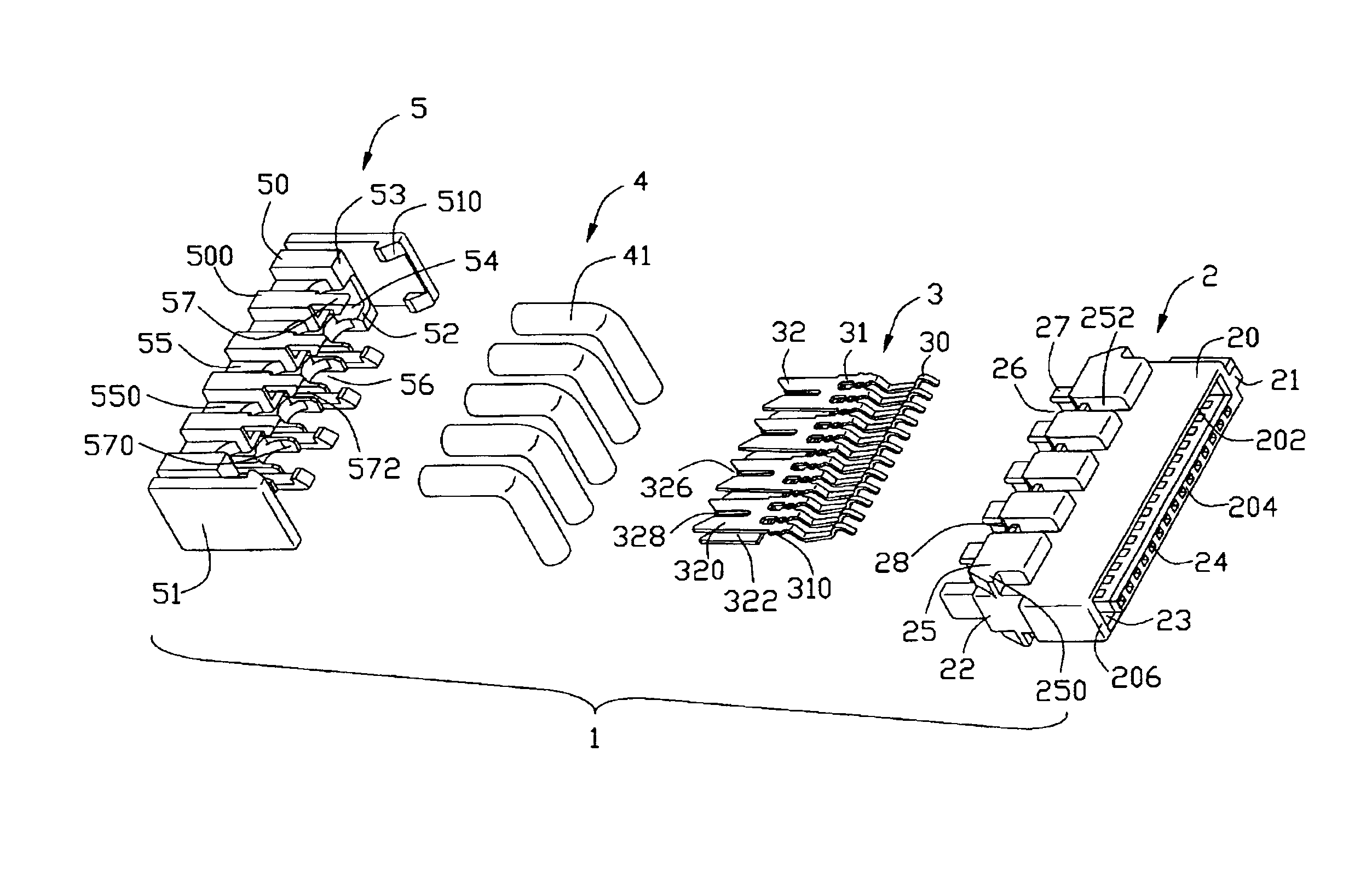
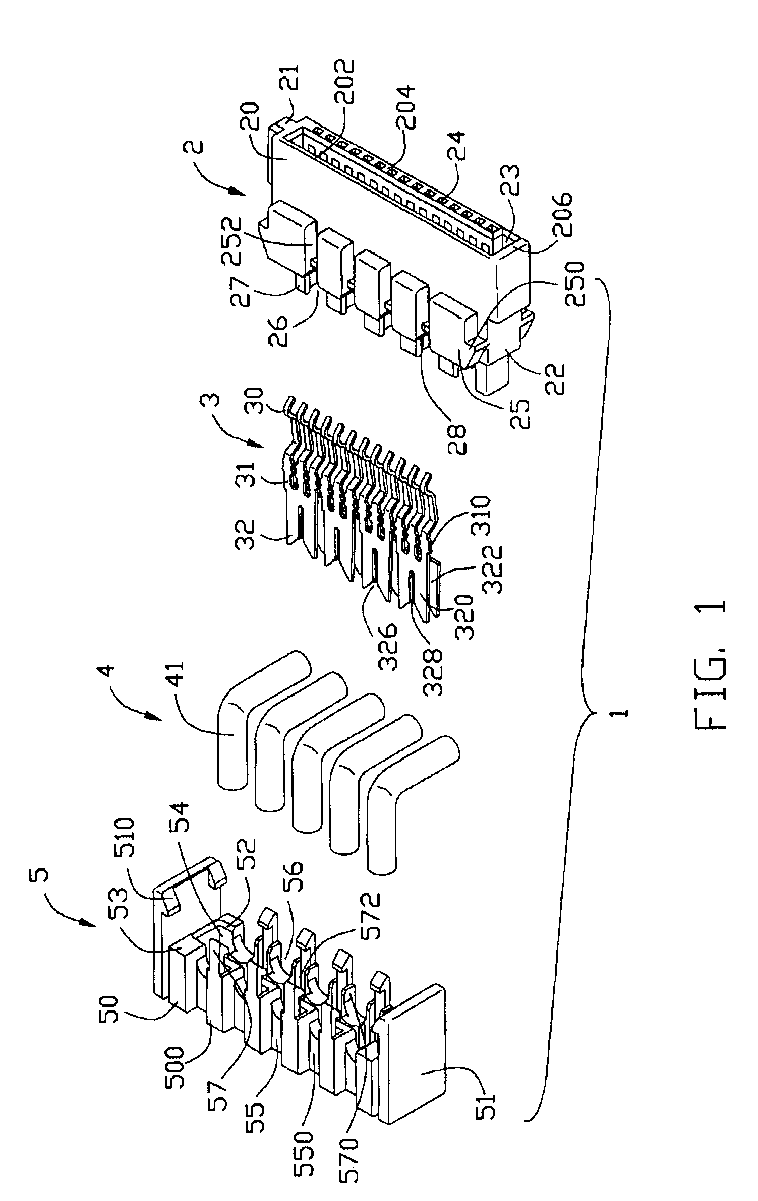
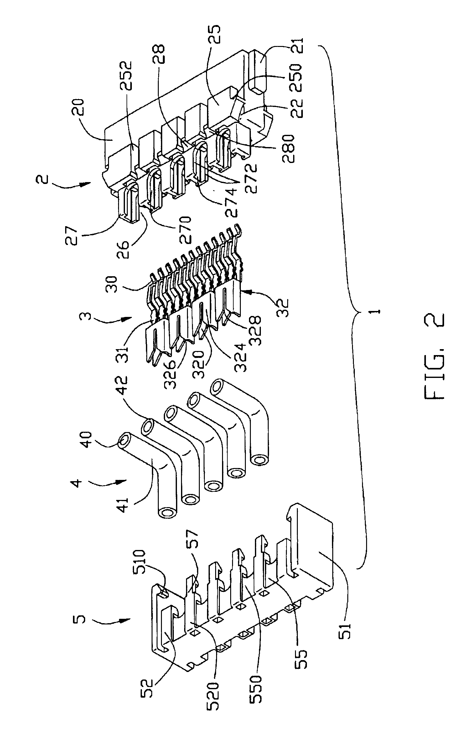
Referring to FIG. 1 and FIG. 2, a cable connector assembly 1 in accordance with the present invention comprises an insulative housing 2, a plurality of contacts 3, a plurality of wires 4, and an insulative cover 5.

The insulative housing 2 comprises a front engaging portion 20 and an opposite terminating portion 22. The insulative housing 2 defines an L-shaped receiving space 22 in the engaging portion 20 circled by an upper wall 202, a lower wall 204, and a pair of lateral walls 206. The lower wall 204 is thicker than the upper wall 202 and defines a plurality of passageways 24 therethrough for receiving the contacts 3. A guiding projection 21 projects sidewardly from one sidewall 206 for facilitating an engagement of the cable connector assembly 1 with a complementary connector. The rear terminating portion 22 comprises a plurality of protrusions 25 respectively formed on an upper surface and a lower surface of the insulative housing 2. Every two neighboring protrusions 25 together...


PUM


Abstract

A cable connector assembly (1) includes an insulative housing (2), a number of contacts (3), a number of wires (4), and a cover (5). The housing has a number of passageways (24) in a front portion (20), and a number of posts (27) and blocks (28) on a rear portion (22). Every two neighboring posts define a contact-receiving tunnel (26) therebetween. Each contact includes an insulation displacement portion (32) received in a corresponding contact-receiving tunnel. The insulation displacement portion includes a first wall (320), a second wall (322), and an intermediate section (324) connecting the opposite walls. The first and the second walls each define a slot (328), and the slots align with each other. Each wire is received in the slots of a corresponding contact in the contact-receiving tunnel. The cover includes a plurality of latching arms (57) respectively engaging with the blocks of the housing.

Description

BACKGROUND OF THE INVENTION1. Field of the InventionThe present invention generally relates to a cable connector assembly, and more particularly to an Insulation Displacement Connection (IDC) cable connector assembly.2. Description of Related ArtIt is common to find the use of IDC technology in the electrical connector industry, because it allows rapid and simple connection of conducting wires to contacts without stripping nor crimping the wires. A typical IDC is made by applying a wire perpendicularly to a planar wall portion of a contact comprising a slot, such that edges of the slot cut through an insulating coating of the wire and make electrical contact with a conductor of the wire. The slots are formed by opposed edges of a sheet metal which is necessarily of a certain width to have sufficient strength to support the contact pressure against the edges.TW patent issue No. 517895 discloses a cable connector assembly which uses IDC technology interconnecting wires and contacts co...

Claims


Application Information

Patent Timeline
Patent Type & Authority Patents(United States)
IPC IPC(8): H01R13/502H01R4/24H01R13/506
CPCH01R12/675H01R4/2429H01R13/506
Inventor LEE, GEORGE
Owner HON HAI PRECISION IND CO LTD
Why Eureka
Try Eureka