Methods and apparatus for mounting an electromagnetic interference shielding cage to a circuit board

a technology of electromagnetic interference and shielding cage, which is applied in the direction of coupling device details, coupling device connection, coupling protective earth/shielding arrangement, etc., can solve the problems of module operation improperly or malfunction, limiting the heat dissipation of the transceiver module, etc., to reduce the cost of circuit board manufacture, minimize the amount of circuit board real estate, cost saving

Inactive Publication Date: 2005-03-15
CISCO TECH INC
View PDF7 Cites 92 Cited by
  • Summary
  • Abstract
  • Description
  • Claims
  • Application Information

AI Technical Summary

Benefits of technology

The conventional shielding cage mounting configuration also affects the spacing between adjacent circuit boards. For example, conventional computer systems have a card cage, or chassis, and a back plane mounted to the card cage configured to provide connection of the circuit boards to the computer system. The card cage holds multiple circuit boards where the planar surfaces of the circuit boards are substantially parallel and where the surface of each circuit board is located at a distance from the surface of an adjoining circuit board. The spacing between the circuit boards is influenced by the height of the shielding cages and transceivers. A relatively large height of the shielding cage relative to the mounting surface of the circuit board requires a relatively large distance between adjacently mounted circuit boards to accommodate for the height of the shielding cage. In turn, increasing the distance between adjacently mounted circuit boards (e.g., to accommodate the height of the shielding cages and transceivers), reduces the number of circuit boards that fit within a mounting space (e.g., within the card cage).
Such a configuration of the slot and module cage carrier also allows for selective population of the circuit board with module cages, thereby providing a cost savings during manufacture of the circuit board. Typically, module cage materials and manufacturing costs are higher than module cage carrier materials and manufacturing costs (e.g., relatively intricate module cages formed from tin-plated beryllium copper material cost more than relatively less intricate module cage carriers formed from cold-rolled steel). Use of the module cage carrier allows attachment of module cages to the circuit board on an as-needed or as-required basis, compared to the conventional approach of fully populating a circuit board with module cages (e.g., potentially overpopulating the circuit board with unused module cages), regardless of the system requirements. Such selective population, therefore, reduces the manufacturing cost of the circuit board.

Problems solved by technology

Conventional techniques for positioning and mounting transceiver module EMI cages to a circuit board suffer from a variety of deficiencies.
Such blockage limits the amount of heat dissipated from the transceiver module contained within the shielding cage.
Heat buildup for a transceiver module, such as an optical transceiver module, can cause the module to operate improperly or malfunction.
The conventional shielding cage mounting configuration also affects the spacing between adjacent circuit boards.
For multiple transceivers in such a configuration, however, multiple rails utilize a relatively large amount of circuit board real estate.

Method used


Image

  • Methods and apparatus for mounting an electromagnetic interference shielding cage to a circuit board
  • Methods and apparatus for mounting an electromagnetic interference shielding cage to a circuit board
  • Methods and apparatus for mounting an electromagnetic interference shielding cage to a circuit board

Examples


Embodiment Construction

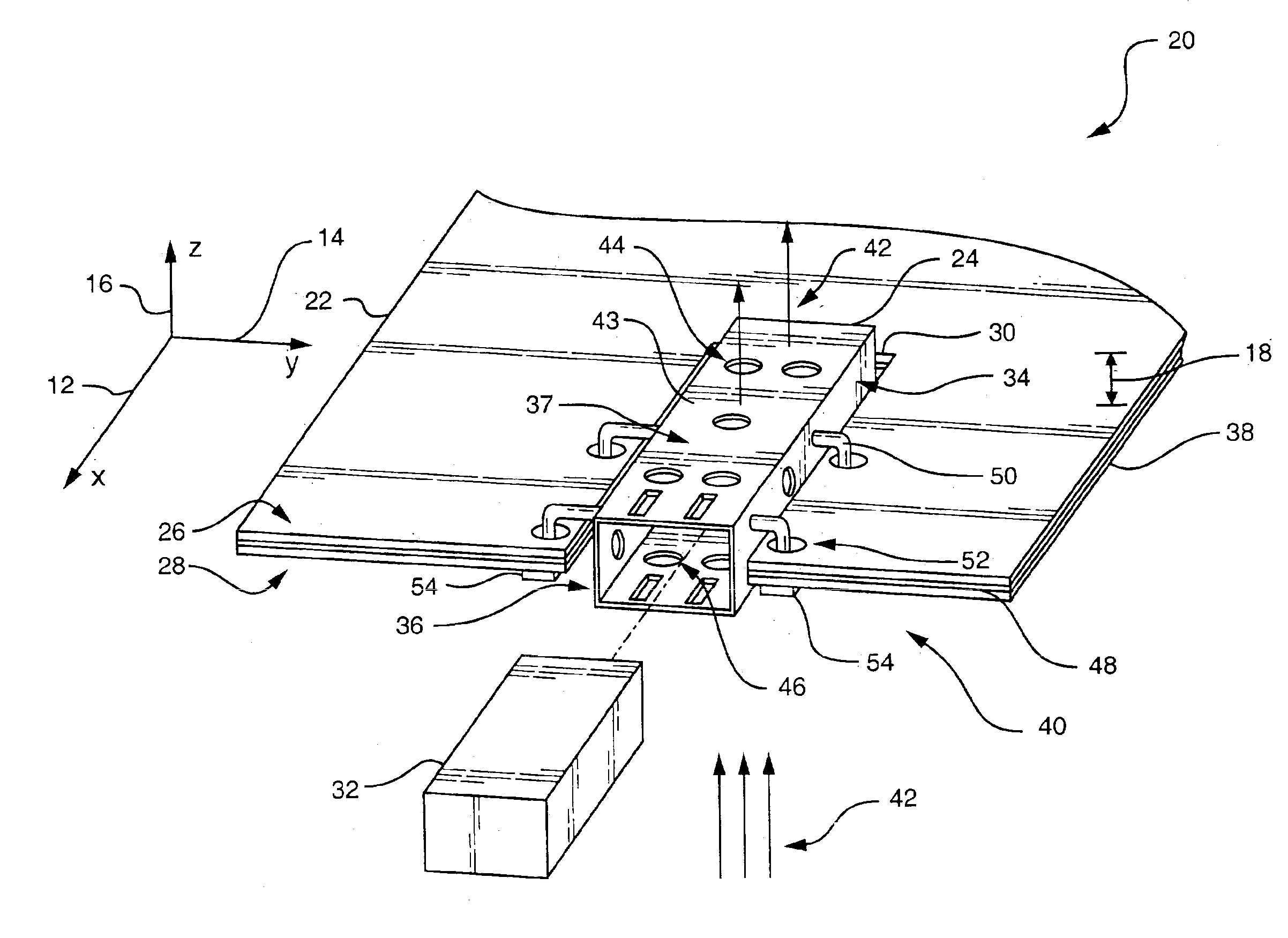
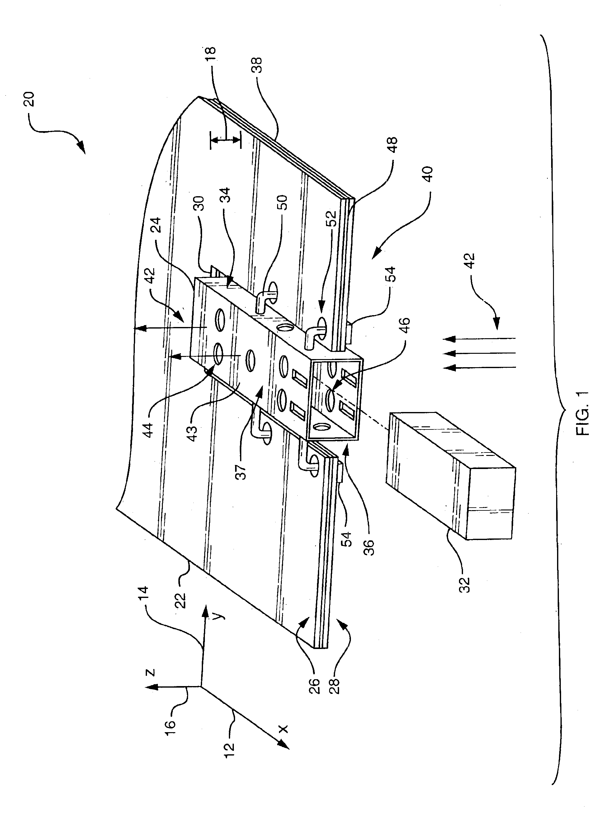
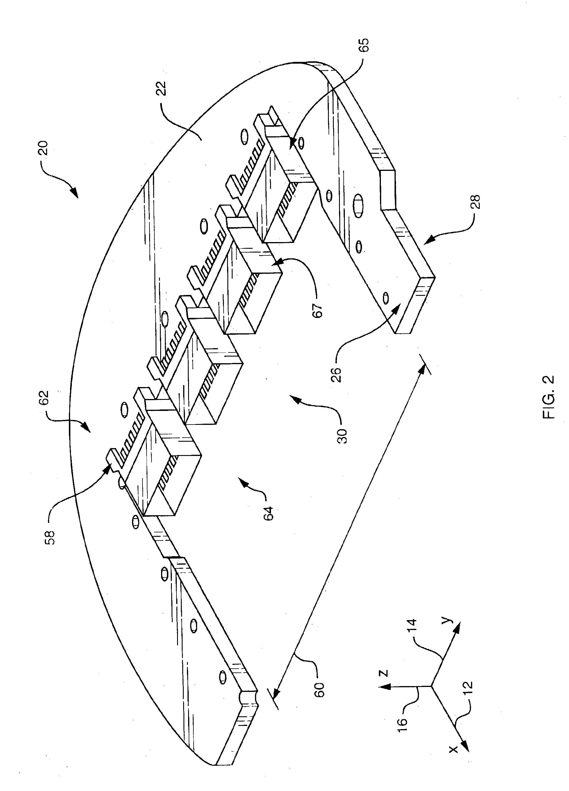
The present invention relates to an EMI shield, or module cage, oriented within a plane of a circuit board such that a first portion of the module cage extends above a first planar surface of the circuit board and a second portion of the module cage extends below a second planar surface of the circuit board. The module cage surrounds a transceiver module and allows airflow to travel across the transceiver module and through the module cage in .a direction substantially perpendicular to a planar surface of the circuit board. Such a configuration aids in cooling of the transceiver module. Also, for a circuit board configured to utilize multiple transceiver modules, multiple module cages attach to the circuit board in a modular configuration. Such a configuration allows attachment, to the circuit board, of the number of module cages corresponding to the number of transceiver modules used by the circuit board (e.g., a circuit board configured to utilize up to four transceiver modules bu...


PUM


Abstract

An EMI shield, or module cage, mounts to a circuit board such that a first portion of the module cage extends above a first planar surface of the circuit board and a second portion of the module cage extends below a second planar surface of the circuit board. The module cage surrounds a corresponding transceiver module and allows airflow to travel across the transceiver module and through the module cage in a direction substantially perpendicular to a planar surface of the circuit board to cool the transceiver module. In one arrangement, multiple module cages attach to the circuit board in a modular configuration. Such a configuration allows attachment, to the circuit board, of the number of module cages corresponding to the number of transceiver modules required or utilized by the circuit board.

Description

BACKGROUND OF THE INVENTIONConventional computerized devices, such as computers communicating over a data communication network, utilize transceivers or modules to both receive and transmit data. For example, computerized devices use optical transceivers to send and receive data in cases where the data communications network requires transmission of the data at relatively high rates of speed. Typical optical transceivers convert light pulses into electrical signals (e.g., for signals received from the network) or convert electrical signals into light pulses (e.g., for signals transmitted to the network).The optical transceivers are normally mounted on a surface of a host printed circuit board (PCB) such as an input / output printed circuit card or a port card connected to an input / output card. In order to facilitate the connection of a fiber-optic cable to the optical transceiver, the transceiver is usually located on a periphery of the host printed circuit board.During operation, con...

Claims


Application Information

Patent Timeline
Patent Type & Authority Patents(United States)
IPC IPC(8): H01R13/658H05K9/00
CPCH05K9/0058H01R13/6594H01R13/659H01R13/6585
Inventor CASEY, KEVINKORDES, KURTFLEMING, STEVENTWISS, ROBERT GREGORYCAP, M. ONDER
Owner CISCO TECH INC
Why Eureka
Try Eureka