Lighting circuit

Inactive Publication Date: 2005-03-15
KOITO MFG CO LTD
View PDF5 Cites 17 Cited by
  • Summary
  • Abstract
  • Description
  • Claims
  • Application Information

AI Technical Summary

Benefits of technology

The summary of the invention does not necessarily describe all necessary features of the present invention. The present invention may also be a sub-combi

Problems solved by technology

Thus, in a case of driving these various lamps by the switching regulator, there was a problem that the switching regulator should be provided for each of the light sources, thus increasing the cost.
In addition, in a case where the current flowing in the light source is limited by using the resistor connected in series with the light source, there was a problem that power consumption of the vehicular lamp increased.

Method used


Image

  • Lighting circuit
  • Lighting circuit
  • Lighting circuit

Examples


Embodiment Construction

The invention will now be described based on the preferred embodiments, which do not intend to limit the scope of the present invention, but exemplify the invention. All of the features and the combinations thereof described in the embodiment are not necessarily essential to the invention.

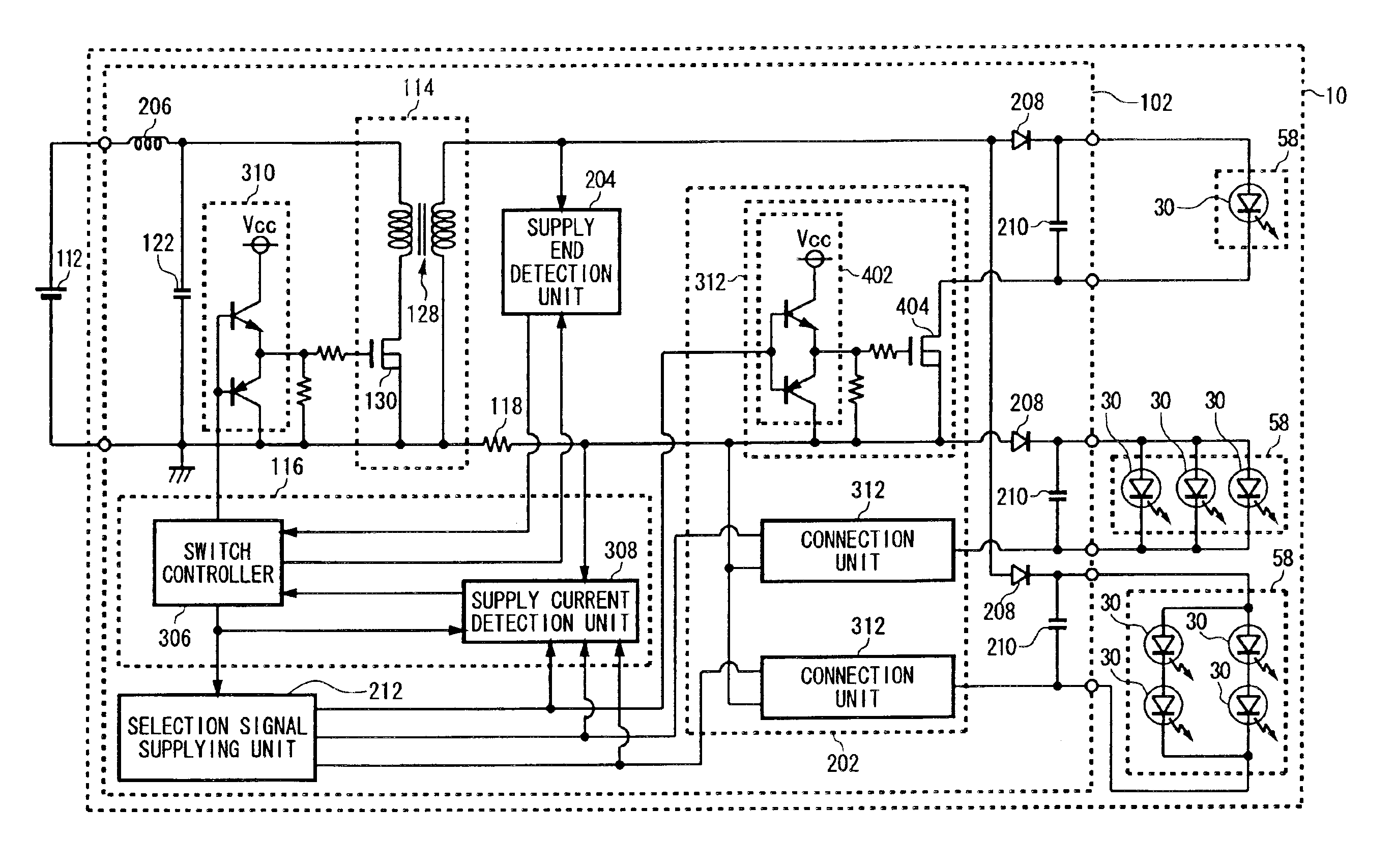
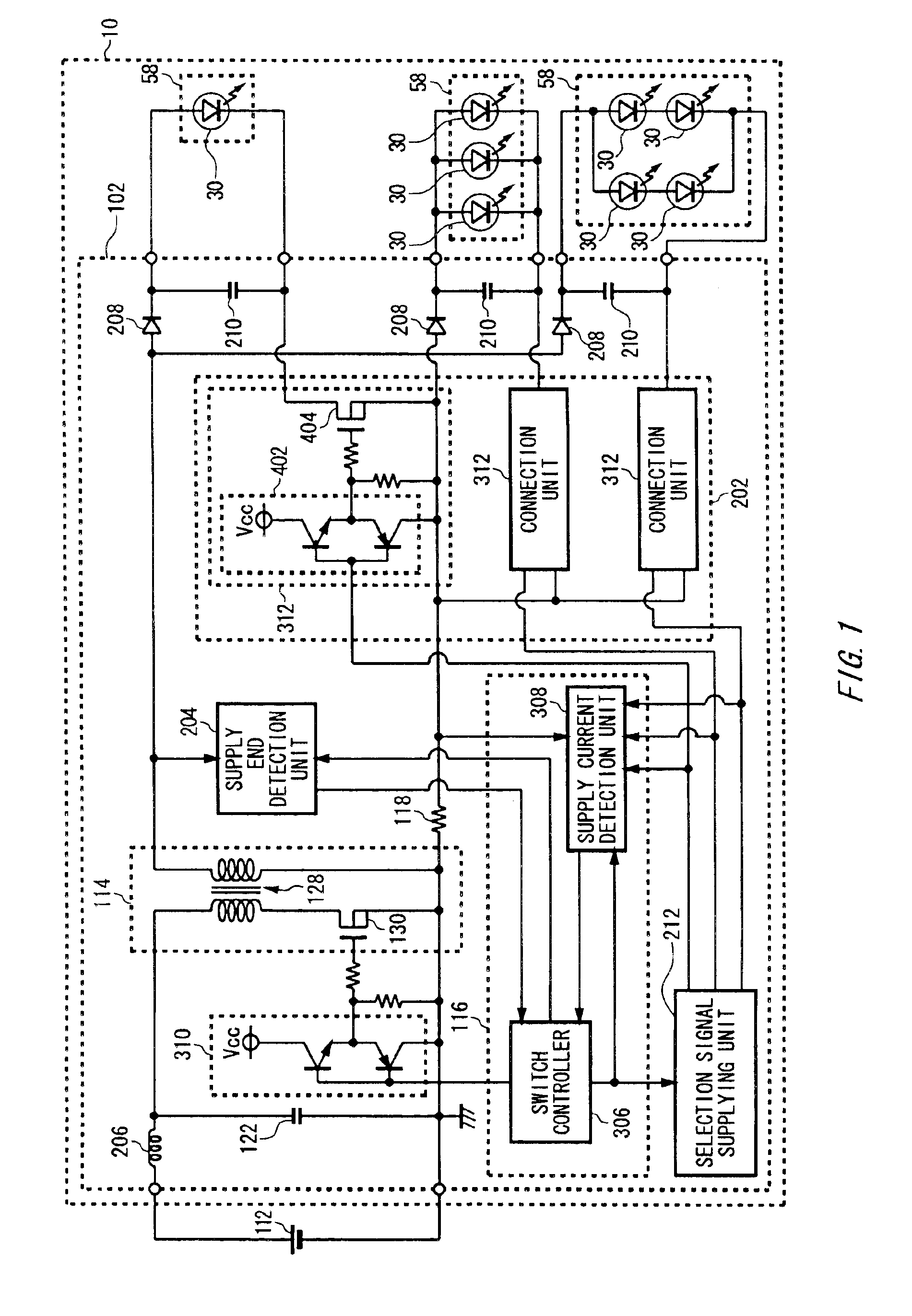
FIG. 1 shows an exemplary circuit structure of a vehicular lamp 10 according to an embodiment of the present invention. The vehicular lamp 10 can supply different currents to a plurality of light source blocks 58. The vehicular lamp 10 includes a plurality of light source blocks 58 and a lighting circuit 102.

The light source blocks 58 include one or more light-emitting diodes 30. The number of the light-emitting diodes 30 contained in one light source block 58 is different from the light source blocks 58. Thus, the light source blocks 58 receive currents that are different in the current amount from the lighting circuit 102.

Each light source block 58 is, for example, a stop lamp, a taillight, a tur...


PUM


Abstract

A lighting circuit for lighting a vehicular lamp including a plurality of light sources each having at least one light-emitting diode, includes: a switching regulator for outputting an output voltage based on a power-supply voltage received from an external DC power supply; a light source selecting unit for selecting the respective light sources one by one and supplying a supply current to a selected one light source by applying the output voltage of the switching regulator to the selected one light source; and an output controlling unit for controlling the output voltage output by the switching regulator to the selected one light source based on the supply current supplied to the selected one light source.

Description

This patent application claims priority from a Japanese patent application No. 2002-295485 filed on Oct. 8, 2002, the contents of which are incorporated herein by reference.BACKGROUND OF THE INVENTION1. Field of the InventionThe present invention relates to a vehicular lamp. More particularly, the present invention relates to a lighting circuit for lighting a vehicular lamp including a plurality of light sources.2. Description of the Related ArtConventionally, a switching regulator that supplies power to a light source of a vehicular lamp is known as disclosed in see Japanese Patent Application Laid-Open No. 2001-215913, page 3 and FIG. 7, for example. An output voltage of the switching regulator is controlled based on a current flowing in the light source, for example. Moreover, a vehicular lamp is known which switches brightness of the light source by switching resistance of a resistor connected in series with the light source as disclosed in Japanese Utility Model Laid-Open No. 6...

Claims


Application Information

Patent Timeline
IPC IPC(8): H05B33/02H05B33/08B60Q1/26B60Q1/00H01L33/00H02M3/28H05B37/02H05B44/00
CPCH05B33/0815H05B33/0848H05B33/0845Y02B20/346H05B45/14H05B45/10Y02B20/30H05B45/3725H05B45/375H05B45/385
Inventor ITO, MASAYASUTAKEDA, HITOSHI
Owner KOITO MFG CO LTD
Why Eureka
Try Eureka