Liquid crystal display device

a liquid crystal display and display device technology, applied in the direction of identification means, electrical apparatus casings/cabinets/drawers, instruments, etc., can solve the problems of increased cost, increased size, and high cost of liquid crystal display devices, so as to reduce the number of components used, suppress the cost, and reduce the cost

Inactive Publication Date: 2005-03-15
VISTA PEAK VENTURES LLC
View PDF7 Cites 47 Cited by
  • Summary
  • Abstract
  • Description
  • Claims
  • Application Information

AI Technical Summary

Benefits of technology

It is an object of the present invention to provide a liquid crystal display device lower in cost and narrower in the picture frame area than in the conventional liquid crystal display devices.
Thus, according to the present invention, it is possible to provide a liquid crystal display device which is lower in cost and narrower in the picture frame area than in the conventional liquid crystal display devices.

Problems solved by technology

However, the above conventional liquid crystal display devices involve the following problems.
First, the liquid crystal display devices are high in cost as compared with displays using cathode-ray tubes.
Also in the liquid crystal display device disclosed in the foregoing Japanese Patent Application Laid Open No. Hei. 11-2813 there is the problem that the cost increases because reflectors are provided for linear light sources respectively.
Further, in the liquid crystal display device disclosed in the foregoing Japanese Patent Application Laid Open No. Hei. 11-146305, it may be possible to suppress an increase in size of a molding machine for fabricating the frame and of a mold used therein, but a limit is encountered in attaining the reduction of cost because the number of components which constitute the frame is large.

Method used


Image

  • Liquid crystal display device
  • Liquid crystal display device
  • Liquid crystal display device

Examples


Embodiment Construction

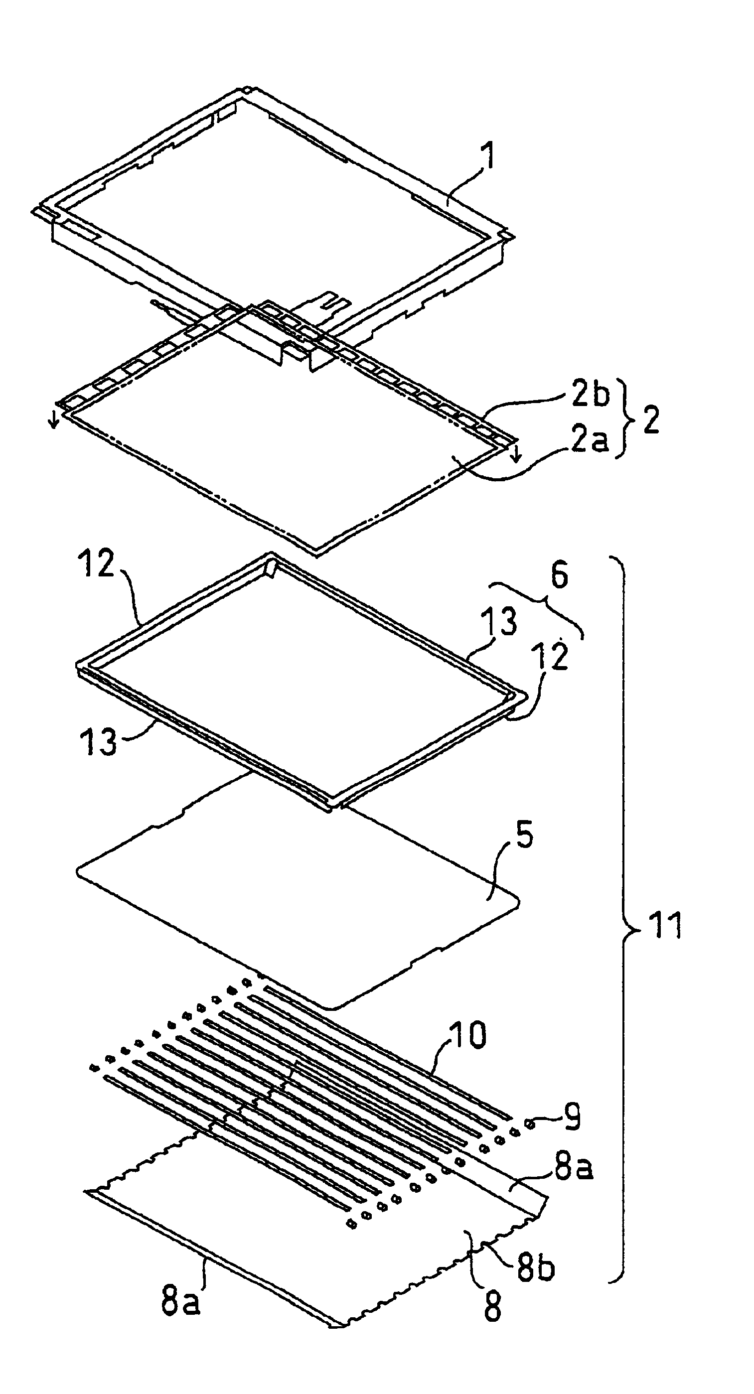
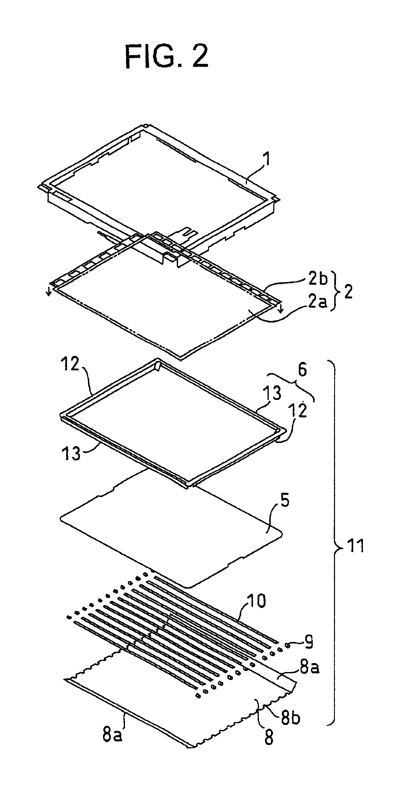
An embodiment of the present invention will be described concretely with reference to the accompanying drawings. FIG. 2 is an exploded assembly diagram showing the construction of a liquid crystal display device according to this embodiment. In the liquid crystal display device of this embodiment, as shown in FIG. 2, a metallic frame 1 of an L-shaped section and a liquid crystal panel 2 are provided. The liquid crystal panel 2 is made up of a display portion 2a which transmits light selectively and which colors to form an image and connecting substrates 2b which are connected to two adjacent sides of the display portion 2a and which controls the operation of the display portion 2a. The display portion 2a is composed of two glass substrates and a polarizer affixed to the outside thereof. The display portion 2a and the connecting substrates 2b are received inside the frame 1 while the connecting substrates 2b are bent at approximately right angles from the display portion. That is, si...


PUM

PropertyMeasurementUnit
angleaaaaaaaaaa
angleaaaaaaaaaa
elasticaaaaaaaaaa

Abstract

In a liquid crystal display device there are provided a frame, a liquid crystal panel, and a diffuser, the liquid crystal panel and the diffuser being supported by a frame formed of a white resin. The frame is composed of two short-side members and two long-side members. The short-side members are provided with reflectors respectively, and lamp mounting members formed of rubber are fitted with the reflectors to support end portions of lamps. The lamp mounting members are mounted to a back reflector to fix the lamps to the back reflector.

Description

BACKGROUND OF THE INVENTION1. Field of the InventionThe present invention relates to a liquid crystal display device provided with a direct backlight and more particularly to a liquid crystal display device which is reduced in the number of components used.2. Description of the Related ArtLiquid crystal display devices are used to constitute a monitor in a thin TV receiver, a stand-alone type monitor, and a monitor in a notebook-size personal computer. A conventional liquid crystal display device is made up of a backlight, a liquid crystal panel which allows light projected from the backlight to pass therethrough selectively and form an image thereon, and a housing which houses therein the backlight and the liquid crystal panel. As backlights there are an edge backlight wherein a light source such as a cold-cathode discharge tube is disposed sideways of a backlight and light emitted from the light source is conducted to a liquid crystal panel by means of a light guide plate and a di...

Claims


Application Information

Patent Timeline
Patent Type & Authority Patents(United States)
IPC IPC(8): G02F1/1335G02F1/13G02F1/1333G02F1/13357G09F9/00
CPCG02F1/133615G02F1/1335
Inventor KANATSU, TSUTOMUISHIDA, HIROSHI
Owner VISTA PEAK VENTURES LLC
Why Eureka
Try Eureka