Methods for robust channel switching of widely-tunable sampled-grating distributed bragg reflector lasers
a distributed bragg reflector and sampled grating technology, applied in the field of wide-tunable lasers, can solve problems such as laser output wavelength dri
- Summary
- Abstract
- Description
- Claims
- Application Information
AI Technical Summary
Problems solved by technology
Method used
Image
Examples
first embodiment
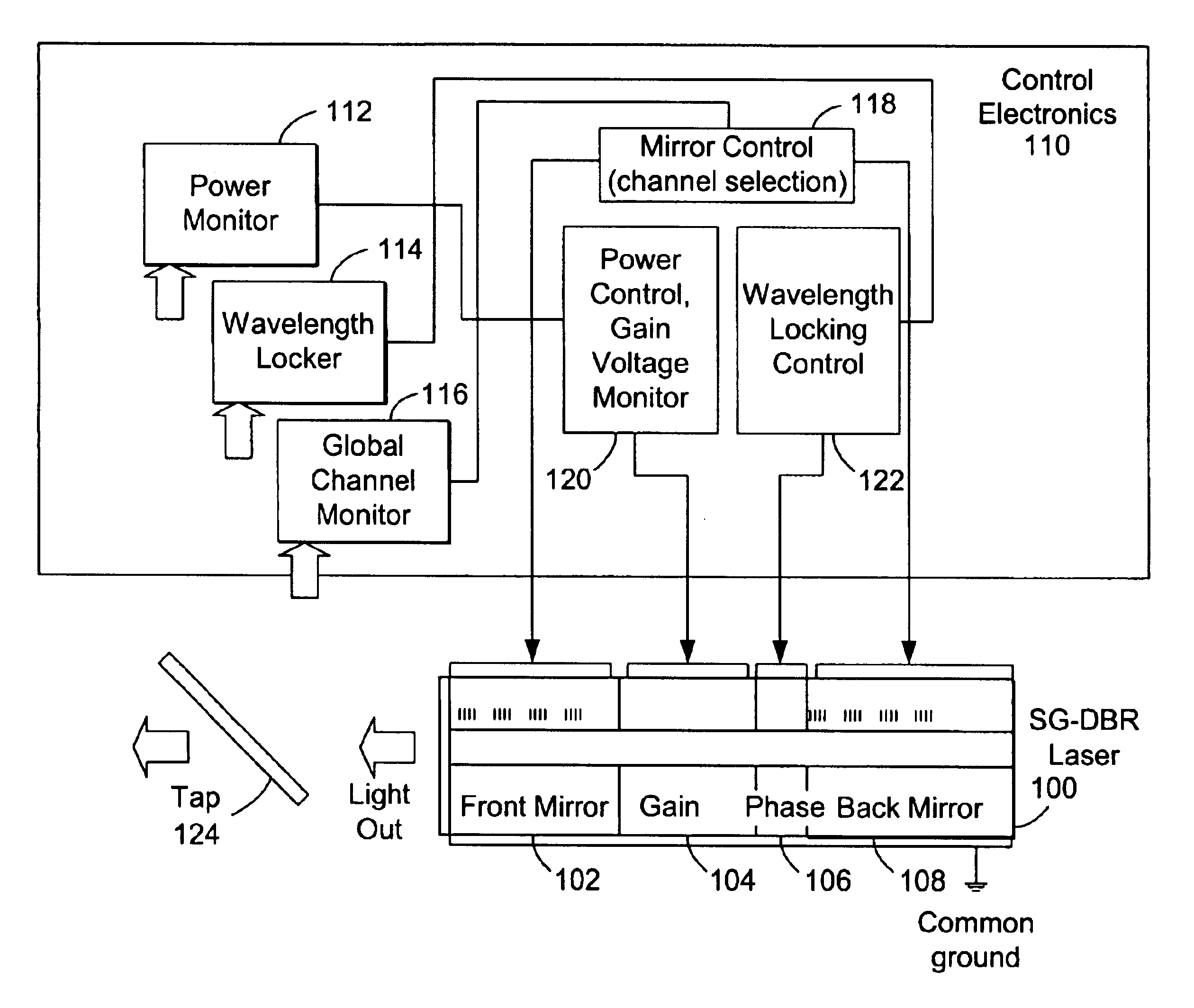
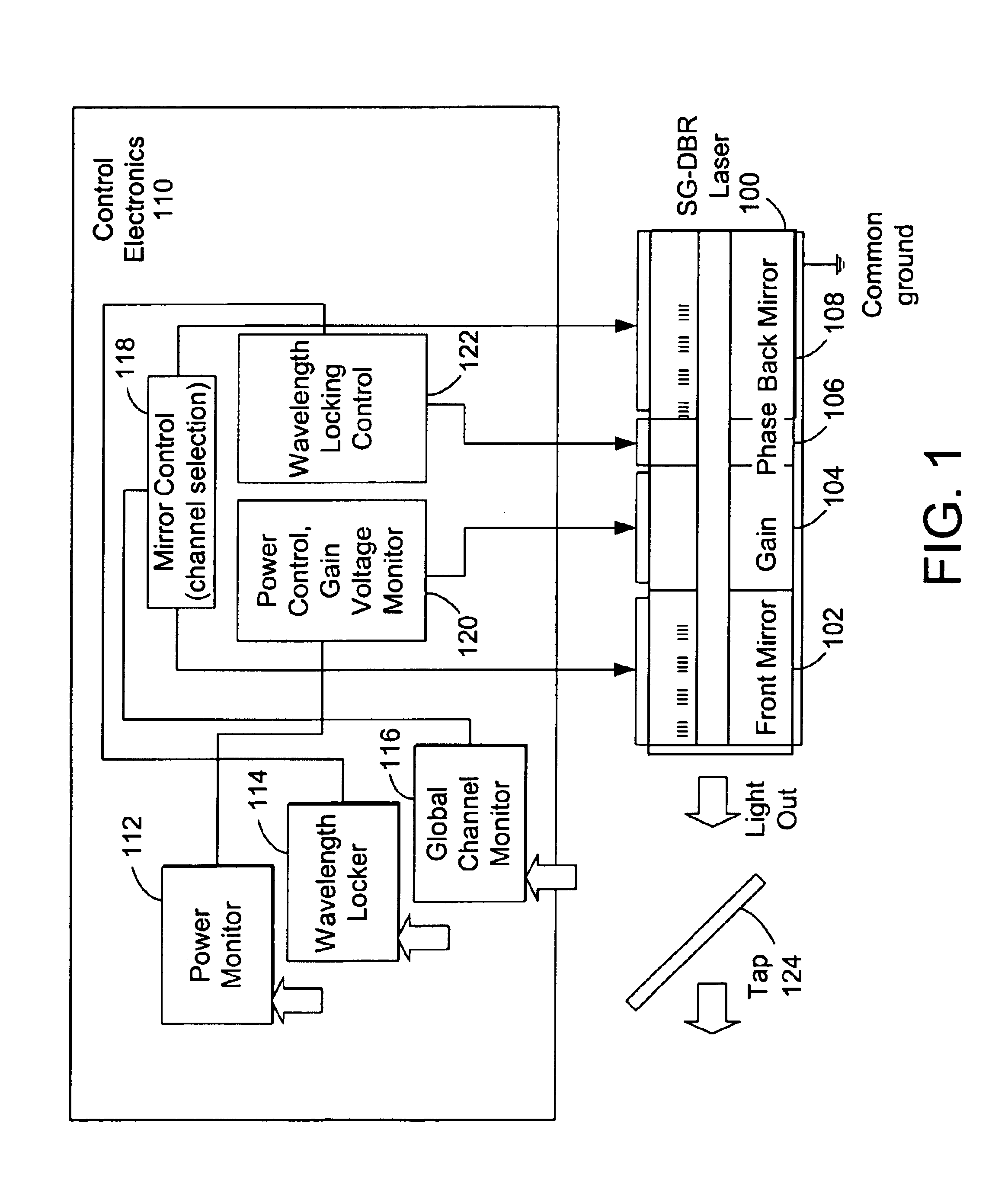
the present invention is a method performed by the control electronics 110 that reliably switches between initial and target channels by counting intermediate cavity mode 302 boundaries or hops. Cavity mode 302 boundaries or hops can be quickly detected using internal techniques, such as discontinuities in gain, phase, or amplifier section voltages, as front and back mirror 102, 108 currents are ramped in a coordinated fashion from the initial channel to the target channel. Comparing the “as-measured” location of cavity mode boundaries or hops with the cavity mode 302 boundaries or hops in the mode map 300, which is obtained at a time zero calibration, results in incremental corrections to the path leading from the initial channel to the target channel. In other words, the front and back mirror 102, 108 currents at the target channel are locked in a relative sense to those of the initial channel through intermediate cavity modes 302 on the mode map 300. The technique includes method...
second embodiment
the present invention is a method performed by the control electronics 110 utilizing an external feedback signal from the global channel monitor 116 that is monotonically related to the wavelength of the output beam of the laser 100. [3] Mode maps 300 in this embodiment are organized in a similar way to the first embodiment. However, instead of ramping the front and back mirror 102, 108 currents in a continuous fashion while monitoring for cavity mode 302 boundaries or hops, the currents are switched instantaneously to an estimate of the front and back mirror 102, 108 currents for the target channel, the wavelength of the output beam is measured by the global channel monitor 116, and a wavelength error is converted to separate current corrections for the front and back mirrors 102, 108. The method uses a time zero calibration to convert the measured wavelength error into separate front and back mirror 102, 108 current corrections for proper target channel acquisition under switching...
PUM
 Abstract
Description
Claims
Application Information
 - R&D
- Intellectual Property
- Life Sciences
- Materials
- Tech Scout
- Unparalleled Data Quality
- Higher Quality Content
- 60% Fewer Hallucinations
Browse by: Latest US Patents, China's latest patents, Technical Efficacy Thesaurus, Application Domain, Technology Topic, Popular Technical Reports.
© 2025 PatSnap. All rights reserved.Legal|Privacy policy|Modern Slavery Act Transparency Statement|Sitemap|About US| Contact US: help@patsnap.com


