

Method and apparatus for image coding and/or decoding using a position and shape map
- Summary
- Abstract
- Description
- Claims
- Application Information
AI Technical Summary
Benefits of technology
Problems solved by technology
Method used
Image

Examples
first preferred embodiment
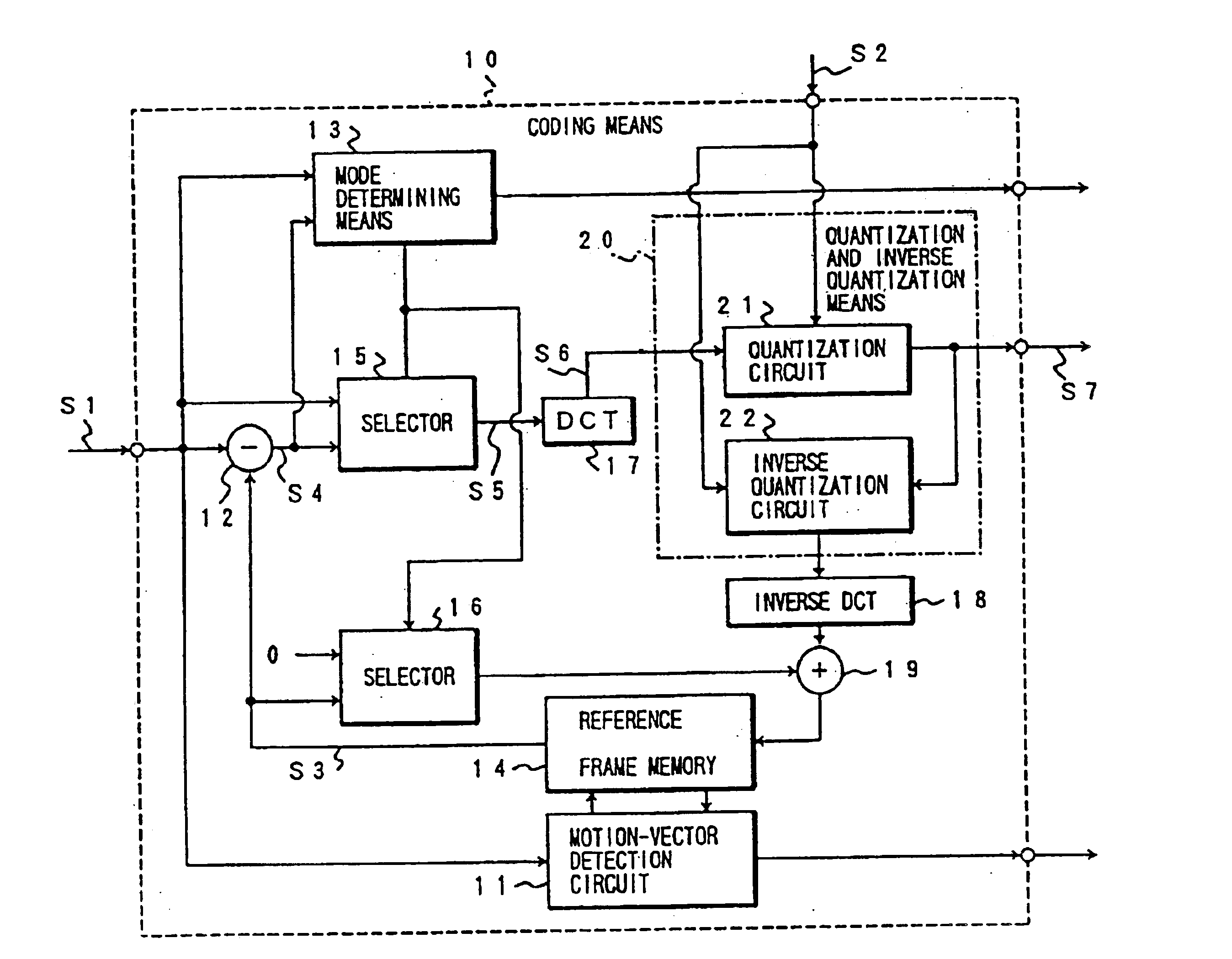
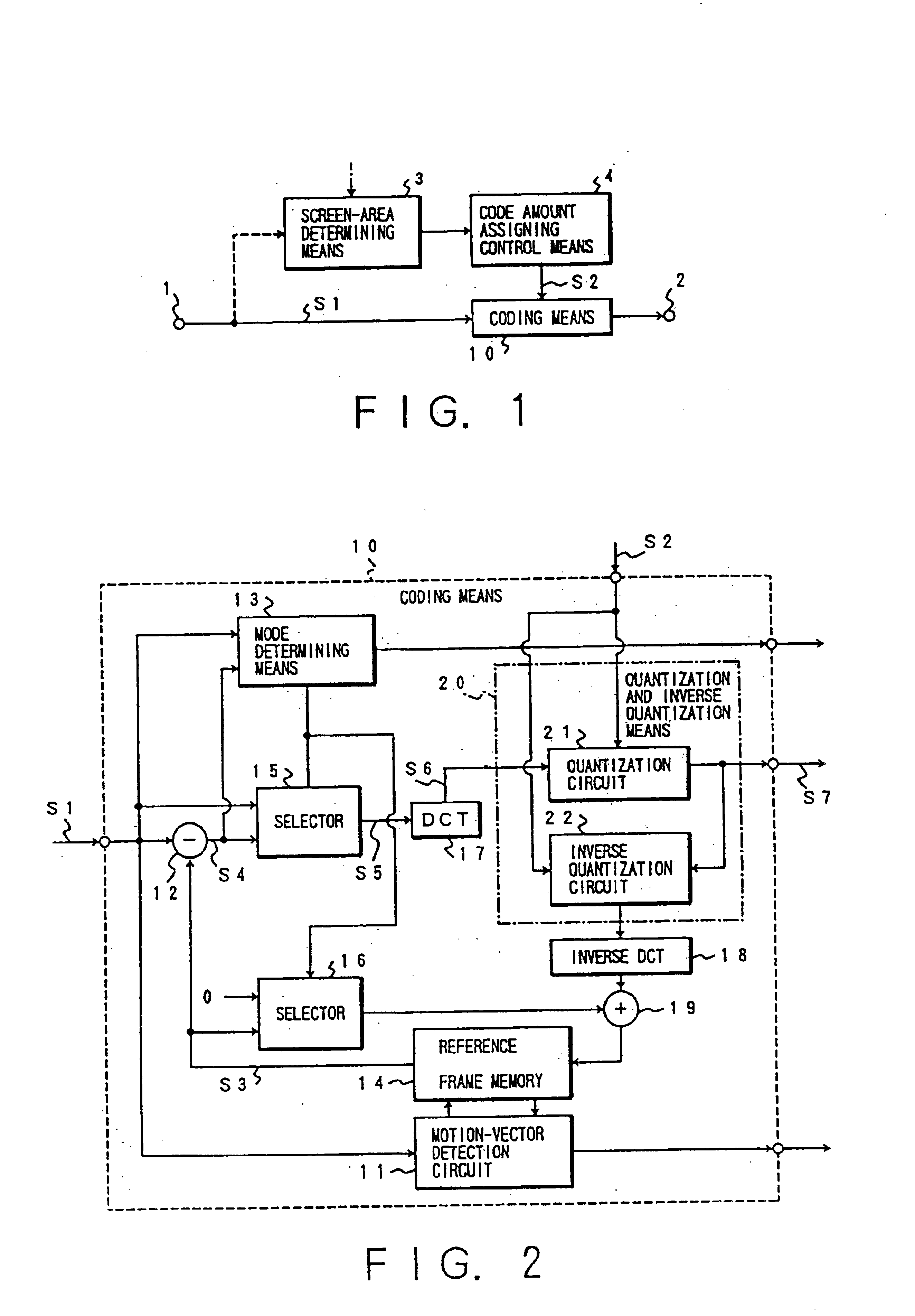
FIG. 20 is a block diagram of the first preferred embodiment of an image data coding system, according to the present invention. An input image signal 10 is divided into a plurality of square blocks by a blocking circuit (not shown) to be supplied to a substraction circuit 100. In the substraction circuit 100, a predicted error signal 30 which is a difference between a motion-compensated prediction signal supplied from a motion-compensated prediction circuit and the input image signal 10, is derived to be supplied to an orthogonal transform circuit 200.
The orthogonal transform circuit 200 transforms the predicted error signal 30 into an orthogonal transform coefficient in accordance with an alpha map signal 20 supplied block by block, and then, supplies the orthogonal transform coefficient to a quantization circuit 120. The quantized coefficient by the quantization circuit 120 is coded by a variable length coding circuit 140, as well as is inversely quantized by an inverse quantizat...
second preferred embodiment
Referring to FIGS. 28 to 34, the second preferred embodiment of an image data coding and / or decoding system, according to the present invention.
FIG. 28 is a block diagram of an image data coding system, according to the present invention. In this embodiment, an orthogonal transform circuit 250 and an inverse orthogonal transform circuit 350 comprise an As-DCT circuit and an AS-IDCT circuit which can switch the orders of the AS-DCT circuit 220 of FIG. 21 and the AS-IDCT circuit 320 of FIG. 22, respectively. A correlation detecting circuit 180 detects a correlation between the components of the predicted error signal 30 in the horizontal and vertical directions, and supplies a signal (a switch signal) 21 indicative of the direction of the high correlation to the orthogonal transform circuit 250, the inverse orthogonal transform circuit 350 and the multiplexer circuit 170. As a method for detecting the correlation in the correlation detecting circuit 180, for example, there is a method...
third preferred embodiment
Referring to FIGS. 37 to 40, the third preferred embodiment of an image data coding and / or decoding system, according to the present invention, will be described below.
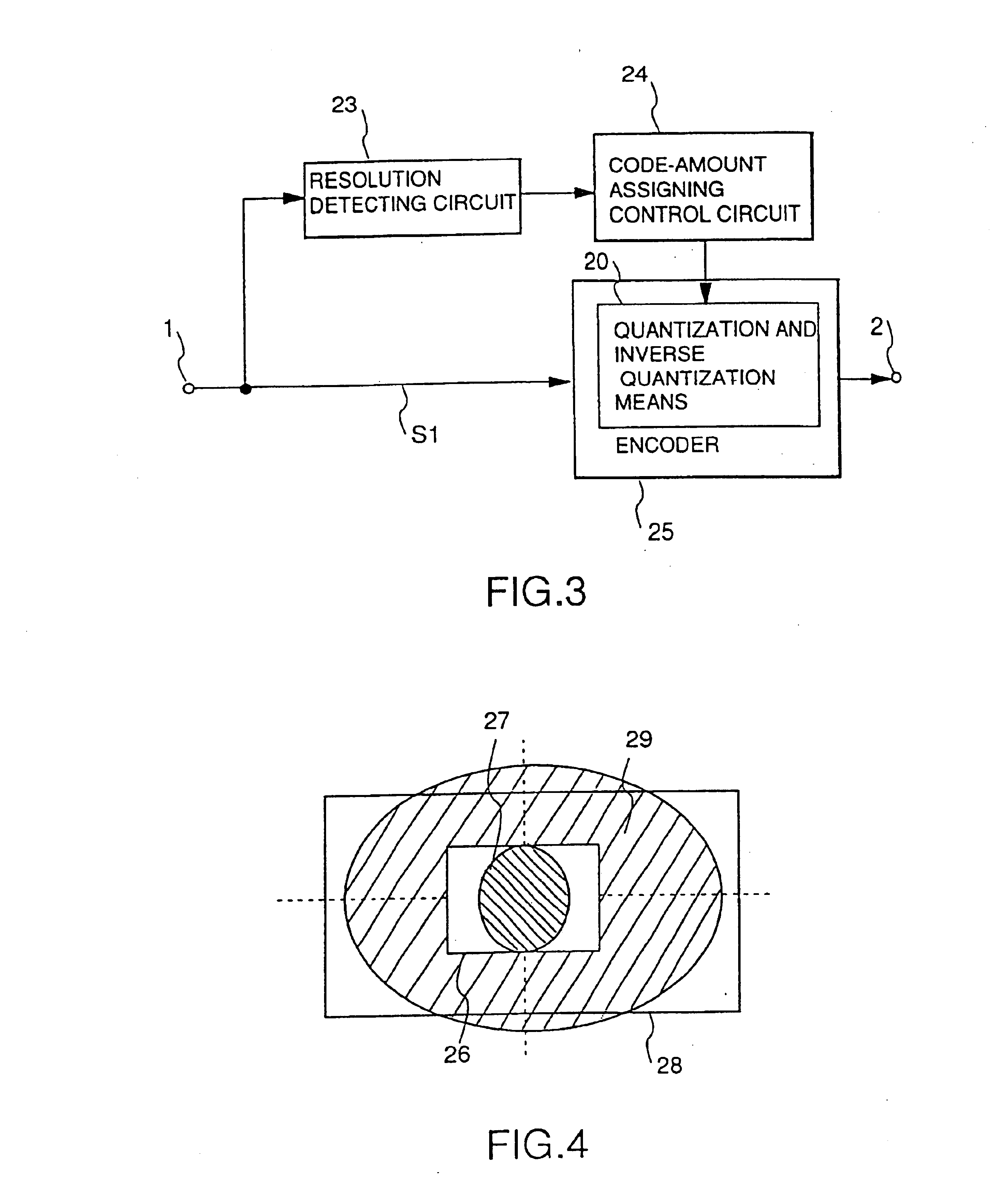
FIG. 37 is a block diagram of an image data coding system in this embodiment. In an average value separating circuit 500, if the predicted error signal 30 is an edge block signal in accordance with the alpha map signal 20, an average value of the signals inside of a content (the portion of oblique lines in FIG. 38) is derived to be separated, and all the signals outside of the content is set to be zero. By this processing, the average value in the central square blocks of FIG. 38 becomes zero. When the signal 32 indicative of the average value 0 in the blocks is supplied to the DCT circuit 230 for performing the two-dimensional DCT, the DC component becomes zero as the right-side square blocks of FIG. 38. In this case, an extrapolated signal may be substituted for the signals outside of the content under the condition...
PUM
 Abstract
Description
Claims
Application Information