Image formation apparatus and a method of controlling the image formation apparatus

a technology of image formation apparatus and control method, which is applied in the direction of electrographic process apparatus, instruments, optics, etc., can solve the problems of image failure and increase the cost, and achieve the effect of preventing the curling of a belt-shaped member and reducing the cos

Inactive Publication Date: 2005-03-15
RICOH KK
View PDF24 Cites 26 Cited by
  • Summary
  • Abstract
  • Description
  • Claims
  • Application Information

AI Technical Summary

Benefits of technology

It is an object of this invention to provide an image formation apparatus which can achieve cost reduction and form a high-quality image by preventing curl of a belt-shaped member.

Problems solved by technology

When this curl occurs, a blank band may occur in an image at the time of primary transfer, which may cause the image to be failed.
However, in case of the apparatus disclosed in Japanese Patent Application-Laid Open H06-289684A, the cost might be increased Because a plurality of position detecting marks have to be provided on the intermediate transfer belt.

Method used


Image

  • Image formation apparatus and a method of controlling the image formation apparatus
  • Image formation apparatus and a method of controlling the image formation apparatus
  • Image formation apparatus and a method of controlling the image formation apparatus

Examples


second embodiment

FIG. 6 is a schematic sectional diagram showing a structure of a main part of an intermediate transfer tandem color image formation apparatus according to this invention.

In FIG. 6, the main part includes four photosensitive drums 100 that rotate in a direction of arrows shown, chargers 200, photosensitive drum cleaning units 300, development units 401 to 404, and an intermediate transfer belt 501A.

On a surface of each photosensitive drum 100 uniformly charged up by the charger 200, color separated optical information corresponding to an image of a document is optically written by irradiating with a laser beam L to form an electrostatic latent image on the surface. Each development unit has a toner of a different color. The electrostatic latent image is developed with the toners of the colors corresponding to the optical information. The developed images of different colors are sequentially superimposed onto and carried on a surface of the intermediate transfer belt 501A by primary t...

fourth embodiment

FIG. 9 is a schematic diagram showing a structure of a full color image formation apparatus according to this invention.

In FIG. 9, the full color image formation apparatus 20 includes image formation units 21C, 21Y, 21M, and 21BK, each forming an image of a different color in accordance with an original image. A transfer section 22 is positioned opposite to the image formation units. A manual feeder tray 23 functions as a sheet medium feeder feeding various sheet media to a transfer region between the image formation units and the transfer section 22 opposing each other. A sheet cassette 24, resist rollers 30 which feed the sheet medium conveyed from the manual feeder tray 23 or the sheet cassette 24 at a timing according to image formation executed by the image formation units 21C, 21Y, 21M, and 21BK, and a fixing device 40 that fixes the sheet material onto which the image has been transferred in the transfer region are also provided in the image formation apparatus 20.

Plain paper...


PUM


Abstract

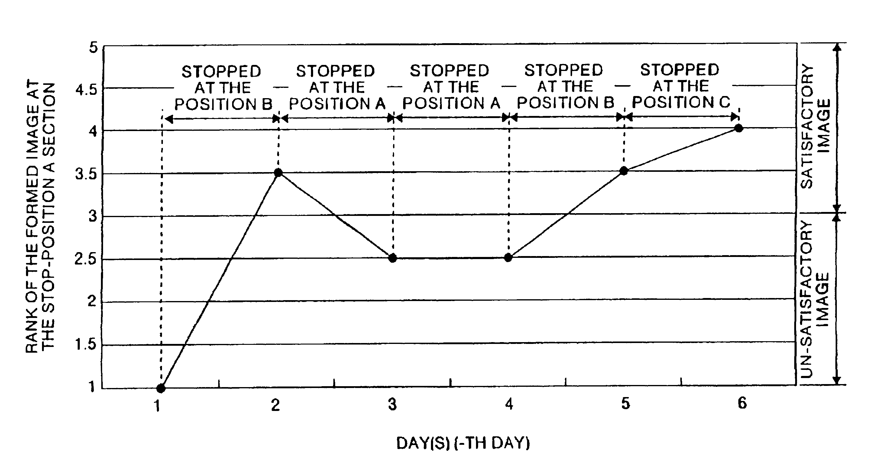
After an image forming operation is finished, a motor that drives a belt is stopped after a predetermined time period passes since a sensor detects the only one mark provided on the belt. The predetermined time period is different for first, second and third jobs. This is repeated for the jobs thereafter. One job is a series of processing from the start of the motor to the stop of the motor. Thus, the belt stops at three different positions, for each consecutive three jobs.

Description

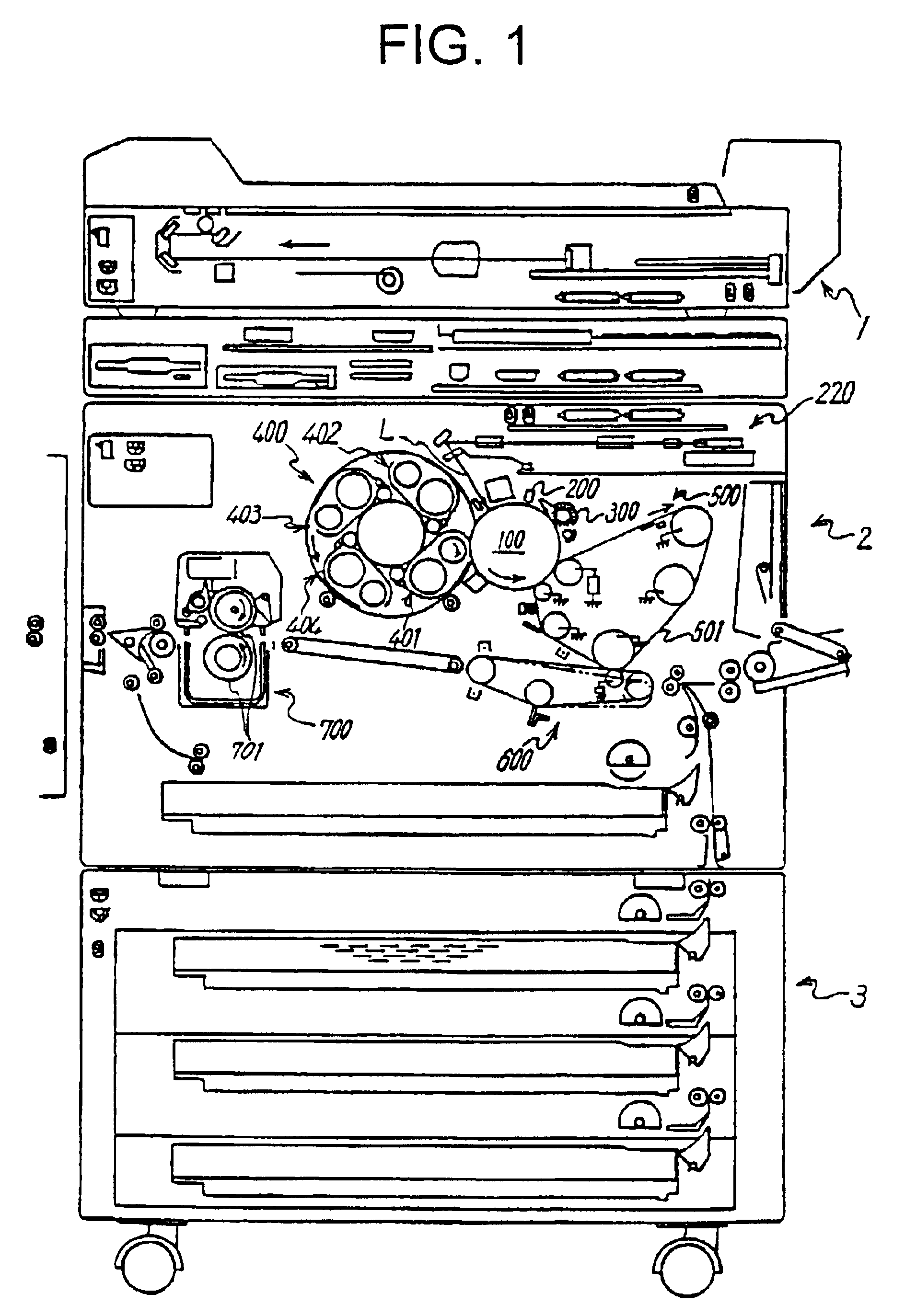
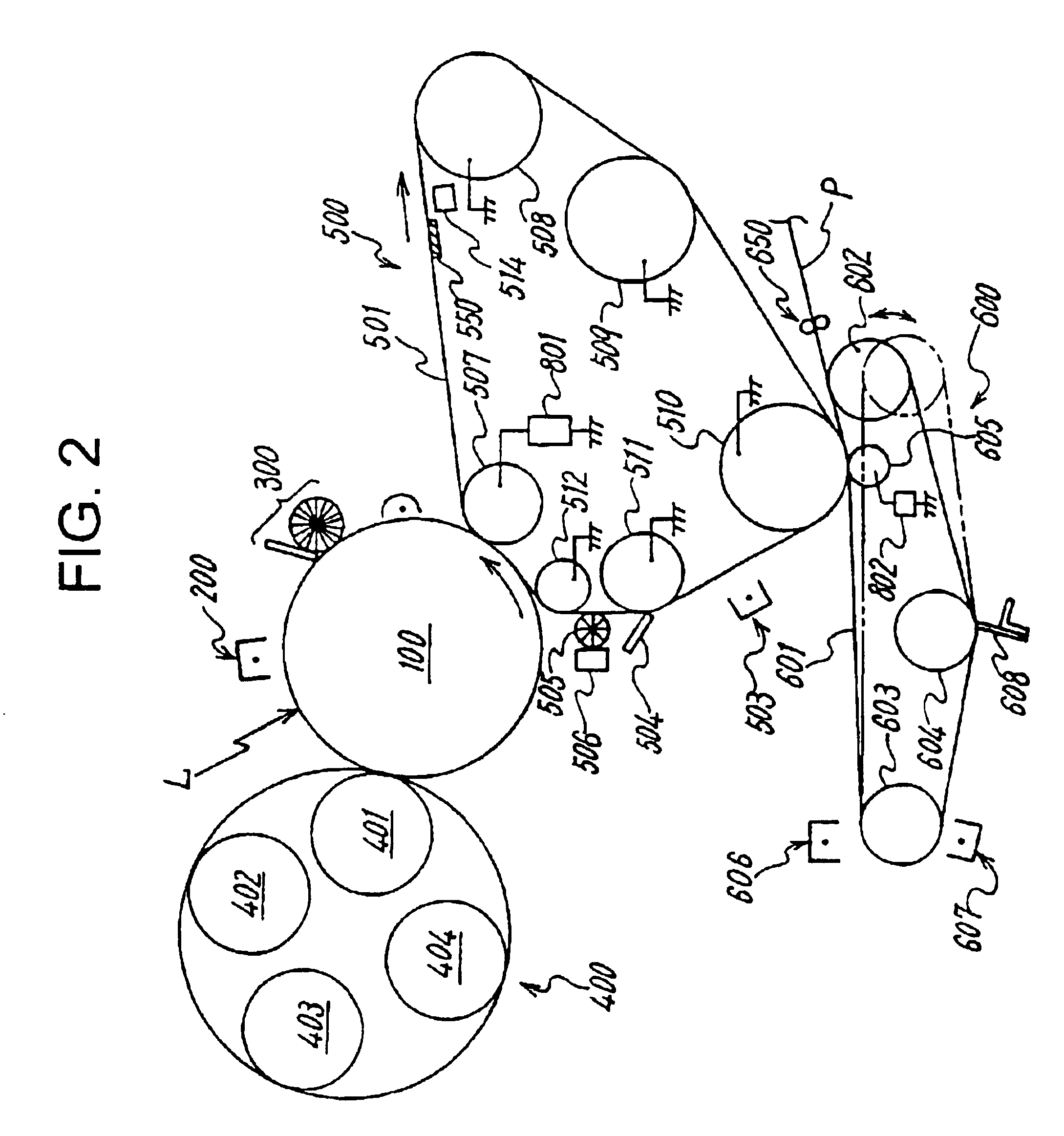
FIELD OF THE INVENTIONThe present invention relates to an image formation apparatus such as a copier, a printer, or a facsimile, and a method of stopping the working of the image formation apparatus after completion of a job. More particularly, this invention relates to the image formation apparatus comprising a belt-shaped member with a mark for position detection, a sensor which detects the mark, a plurality of holding members which hold the belt-shaped member rotatably, and a drive unit that drives the belt-shaped member.BACKGROUND OF THE INVENTIONConventionally, there has been known an image formation apparatus using a belt-shaped member as one of its components. For example, there is one which has an intermediate transfer belt disposed opposite to a photosensitive body formed with a rotator rotatably driven, and rotated at the same peripheral speed as that of the photosensitive body, with which the belt is kept contact during the rotation. This type of image formation apparatus...

Claims


Application Information

Patent Timeline
Patent Type & Authority Patents(United States)
IPC IPC(8): G03G15/01
CPCG03G15/0131G03G2215/0177
Inventor FUKAO, TAKESHITAKAHASHI, MITSURU
Owner RICOH KK
Why Eureka
Try Eureka