
Method and apparatus for estimating carrier frequency offset and fading rate using autoregressive channel modeling

a carrier frequency offset and channel modeling technology, applied in the field of advanced algorithms for radio receivers, can solve the problems of transmitters at base stations or mobile terminals that are typically fading dispersive communication channels, and transmitters and receivers that are limited in adaptivity to varying communication channel conditions

Inactive Publication Date: 2005-03-15
NOKIA TECHNOLOGLES OY
View PDF4 Cites 31 Cited by
  • Summary
  • Abstract
  • Description
  • Claims
  • Application Information

AI Technical Summary

Problems solved by technology

Thus, a signal transmitted by a transmitter at either a base station or a mobile terminal undergoes distortion (change in amplitude and phase) due to changing destructive interference among changing multiple propagation paths to a receiver, in what is known as (time-varying) multipath fading.
Thus, mobile channels are typically fading dispersive communication channels.
In addition, it is often assumed that the channel impulse response is independent for different values of delay, in which case the channel is said to exhibit uncorrelated scattering of the transmitted signal.
In current communication systems, the adaptivity of the transmitter and receiver to varying communication channel conditions is limited.
As far as is known to the inventor, there does not exist in the prior art any reliable and computationally feasible method for estimating fading rate in case of general multipath fading.
For estimating carrier frequency offset, the prior art does teach some methods but the performance of the prior art frequency offset estimation methods in high bit-rate and high mobility applications is generally unknown, and the inventor knows of no prior art teaching of obtaining the offset from a statistical autoregressive model of a communication channel.
In particular, the prior art does not teach how to estimate jointly the fading rate and frequency offsets for different multipath signal components in a computationally feasible way.

Method used


Image

  • Method and apparatus for estimating carrier frequency offset and fading rate using autoregressive channel modeling
  • Method and apparatus for estimating carrier frequency offset and fading rate using autoregressive channel modeling
  • Method and apparatus for estimating carrier frequency offset and fading rate using autoregressive channel modeling

Examples


Embodiment Construction

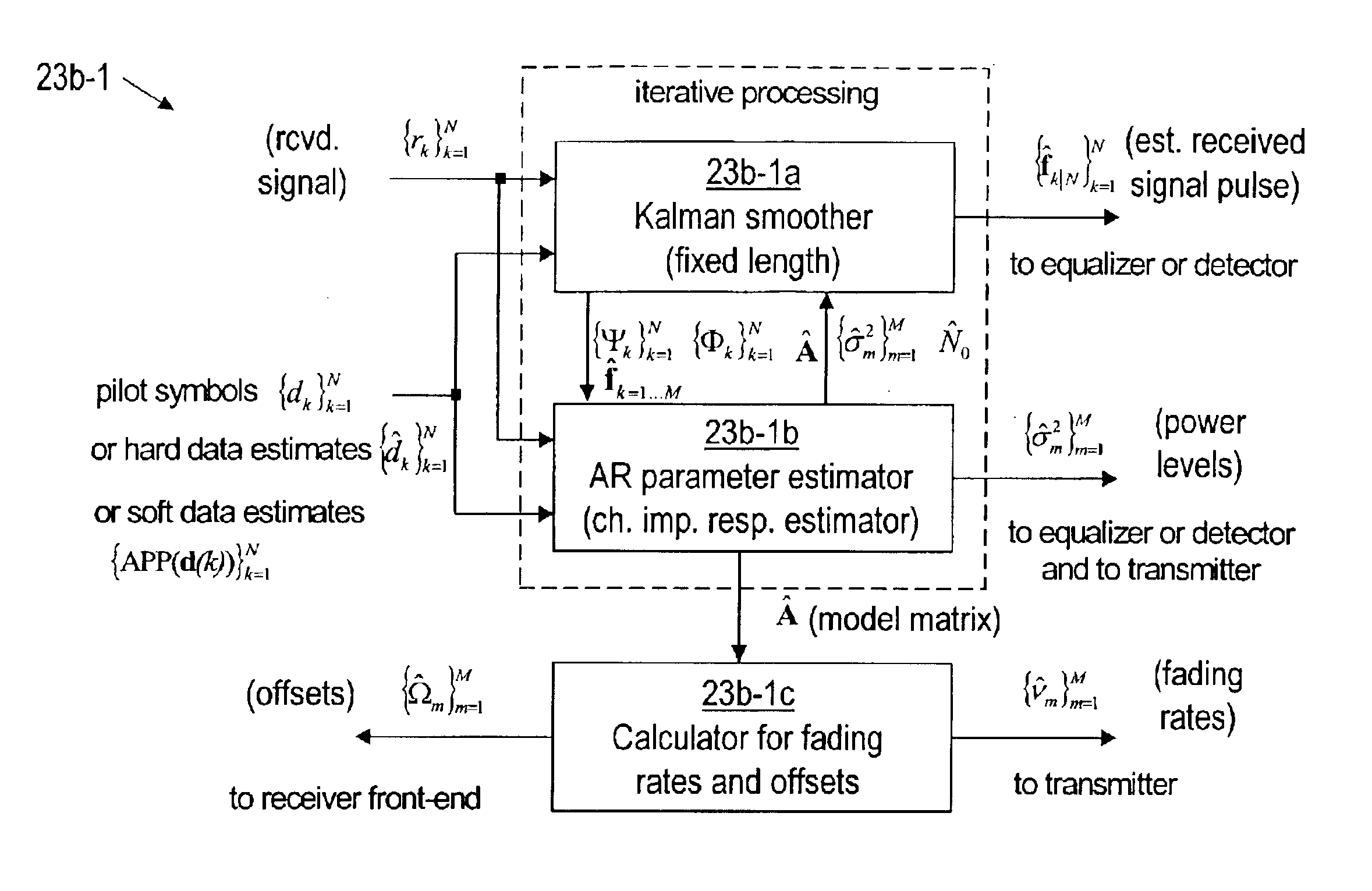
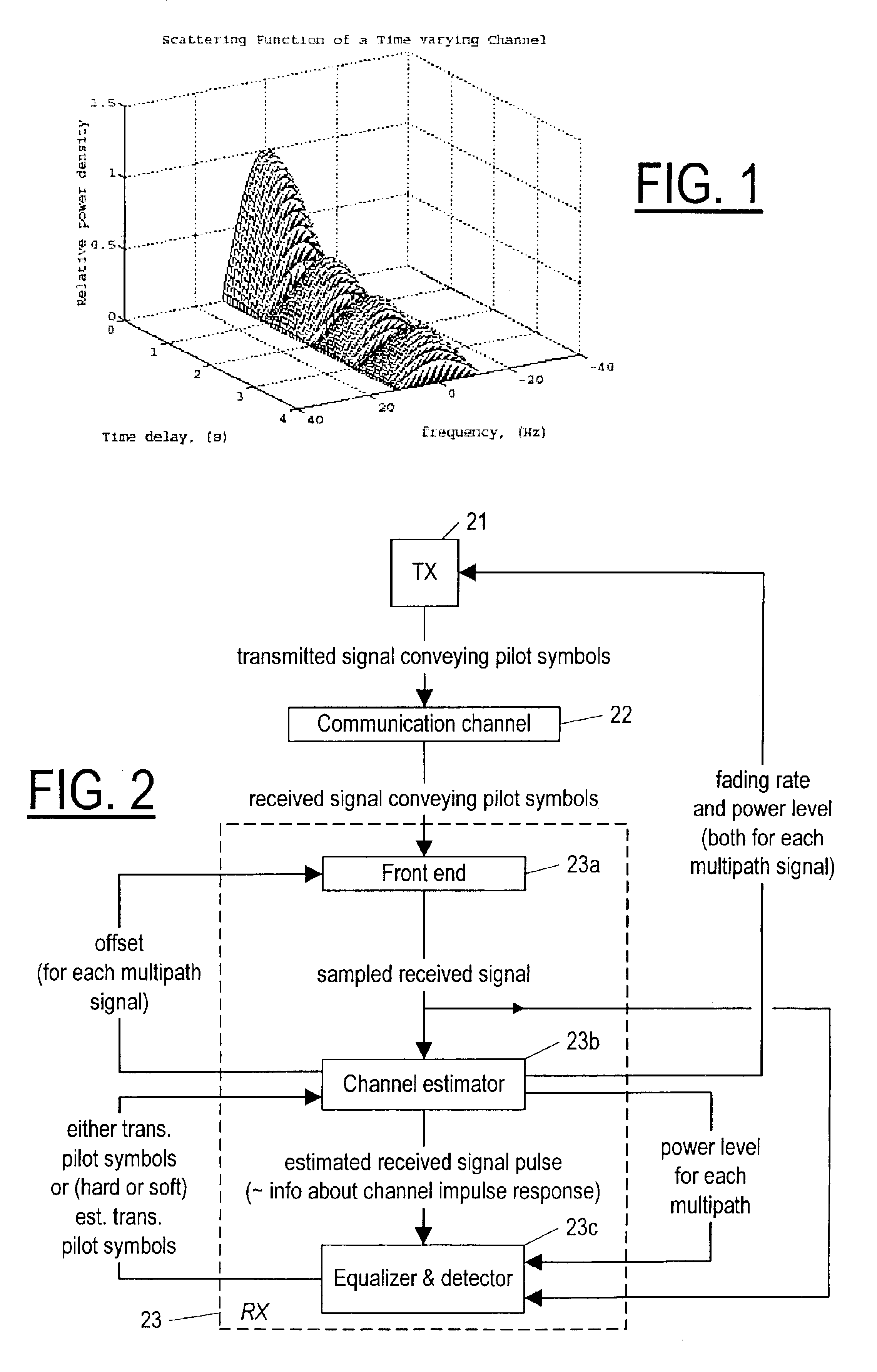
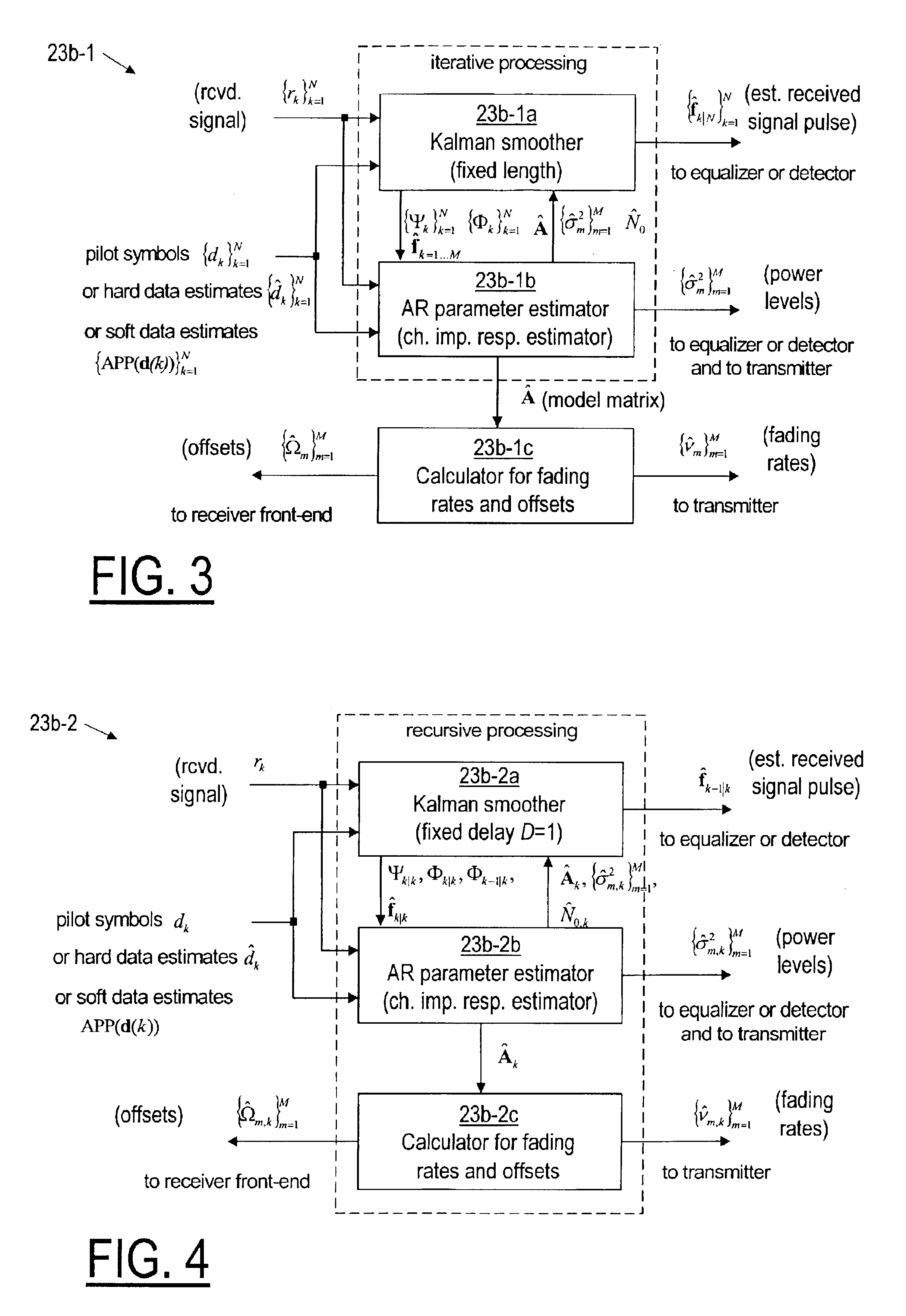
Referring now to FIG. 2, according to the invention, a receiver (RX) 23 receives a signal conveying pilot symbols transmitted by a transmitter 21 over a communication channel 22, assumed to be a fading dispersive communication channel, and then, using a predetermined parametric model that is preferably an autoregressive model, the receiver 23 estimates, for each of possibly several resolvable multipath signals, a fading rate, an offset, and a power level, as described below. The receiver 23 includes a front end 23a, a channel estimator 23b, and a module 23c that preferably includes an equalizer and a detector, but at least includes a detector. The front end 23a provides to the channel estimator 23b and to the module 23c samples of the received signal. The detector component of the equalizer and detector module(s) 23c provides to the channel estimator 23b either the a priori known pilot symbols (training symbols) or (hard or soft) estimated transmitted pilot symbols. Using the pilot ...


PUM


Abstract

A method for use by a receiver of a wireless communication system in providing information of use in adapting to changing characteristics of a communication channel (22) over which the receiver (23) receives a signal at an offset from a carrier frequency due to changes in the characteristics of the communication channel characteristics, the changing communication channel characteristics also causing from time to time changes in other characteristics of the communication channel (22), the method characterized by: a step (23b-1a 23b-1b) of providing expectation maximization estimates of autoregressive parameters representing the changing communication channel (22) using received signal samples extracted from the received signal and corresponding to transmitted pilot symbol; and a step (23b-1a 23b-1c) of providing an estimate of the channel impulse response and an estimate of a frequency offset of at least one multipath signal based on the estimated values of the autoregressive parameters.

Description

FIELD OF THE INVENTIONThe invention relates to the general area of advanced algorithms for radio receivers used in wireless communications, and more particularly to such algorithms for use in high bit-rate high mobility communication systems.BACKGROUND OF THE INVENTIONAn important feature of state-of-the-art and newly emerging communication systems (e.g. enhanced so-called third generation and later generation wireless telecommunication systems according to the third generation partnership program for the universal mobile telecommunication system) is a capability of both wireless transmitters and receivers to adapt their functionality and parameters according to prevailing channel conditions. Channel conditions in mobile communications change for example because as a mobile station changes location and as objects that scatter a mobile signal move about, the communication signal between the mobile station and the base station is differently reflected, refracted, and diffracted, givin...

Claims


Application Information

Patent Timeline
Patent Type & Authority Patents(United States)
IPC IPC(8): H04B1/16H04B15/00H04LH04L1/00H04L25/02
CPCH04L1/0026H04L25/0236H04L25/0212H04L25/0222H04L1/0036H04L1/0003H04L1/0009
Inventor NISSILA, MAURI
Owner NOKIA TECHNOLOGLES OY
Learn More