
Mixed waveform configuration for wireless communications

a wireless communication and waveform technology, applied in data switching networks, phase-modulated carrier systems, baseband system details, etc., can solve problems such as multi-path distortion, incompatibility of system implementation according to 802.11a and 802.11b standards, and inability to work together, so as to achieve the effect of reducing complexity

Active Publication Date: 2003-01-16
INTELLECTUAL VENTURES I LLC
View PDF23 Cites 58 Cited by
  • Summary
  • Abstract
  • Description
  • Claims
  • Application Information

AI Technical Summary

Benefits of technology

0011] The power, carrier phase, carrier frequency, timing, and multi-path spectrum may be substantially maintained between the first portion and the second portion of the waveform. One way to facilitate this goal is to employ a single-carrier spectrum that resembles a multi-carrier spectrum of the multi-carrier modulation scheme in the single-carrier modulation scheme. For example, the single-carrier spectrum has a dominant peak in its impulse response with a relatively small amount of spread. In particular configurations, the single-carrier spectrum has a nearly flat spectrum with sufficiently steep roll-off on its edges, or the single-carrier spectrum employs a time shaping pulse that is specified in continuous time. The time shaping pulse may have a relatively short duration. The time shaping pulse may be derived...

Problems solved by technology

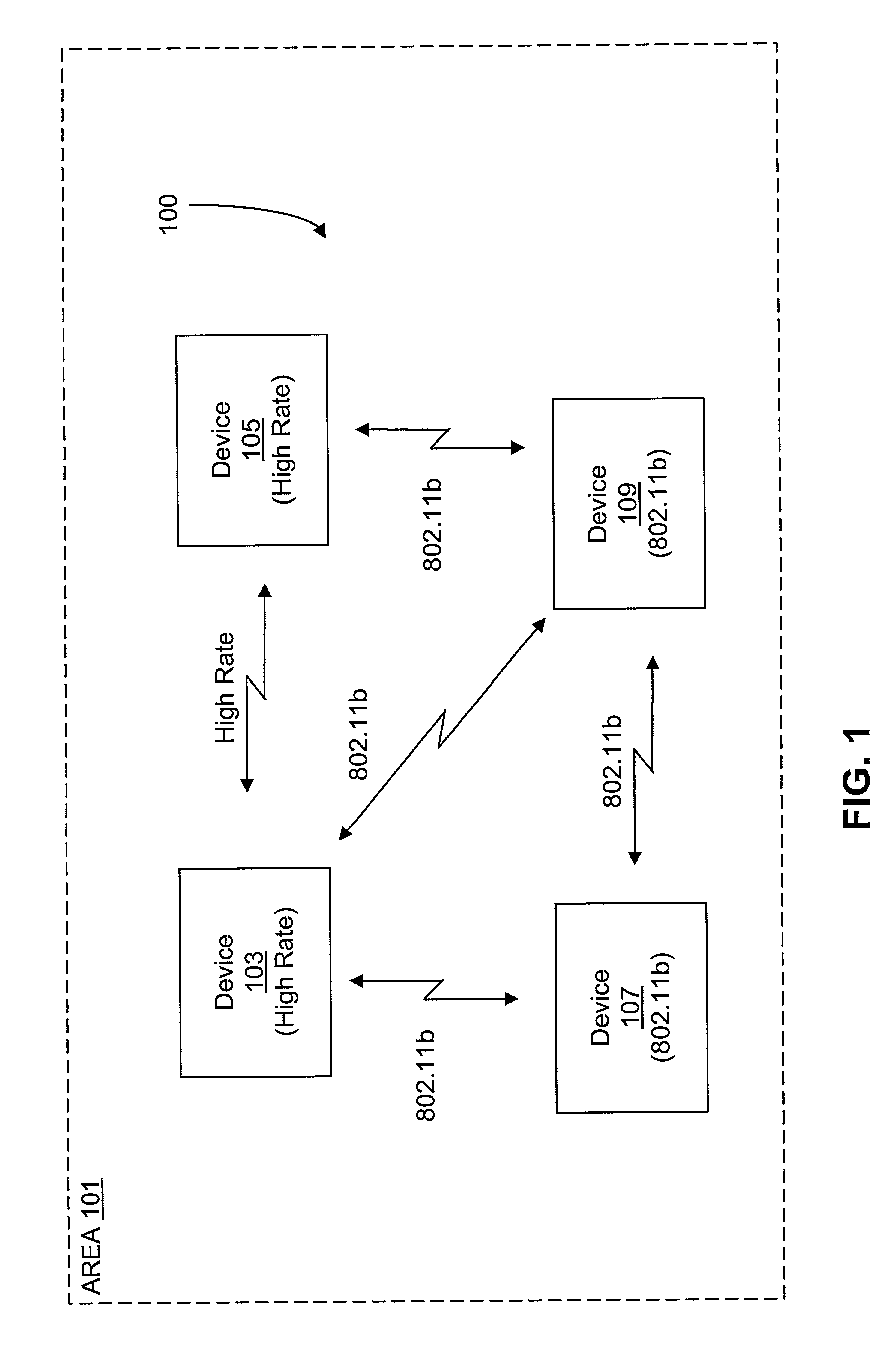
It is noted that systems implemented according to the 802.11a and 802.11b standards are incompatible and will not work together.
Several significant technical challenges are presented for the new 802.11g proposal.
An impairment to wireless communications, including WLANs, is multi-path distortion where multiple echoes (reflections) of a signal arrive at the receiver.
Interference is a serious problem with WLANs.
Systems implemented according to the Bluetooth standard present a major source of interference for 802.11-based systems.
Hence, losing all information when transitioning from single-carrier to multi-carrier is not desirable in the presence of interference.
There are several potential problems with the signal transition, particularly with legacy equipment.

Method used


Image

  • Mixed waveform configuration for wireless communications
  • Mixed waveform configuration for wireless communications
  • Mixed waveform configuration for wireless communications

Examples


Embodiment Construction

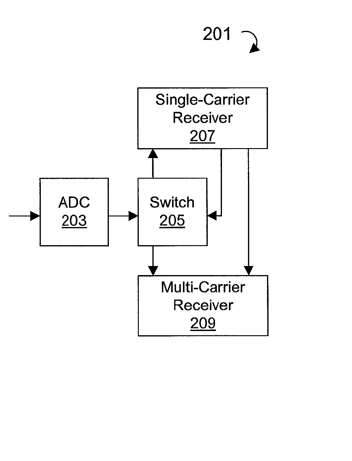
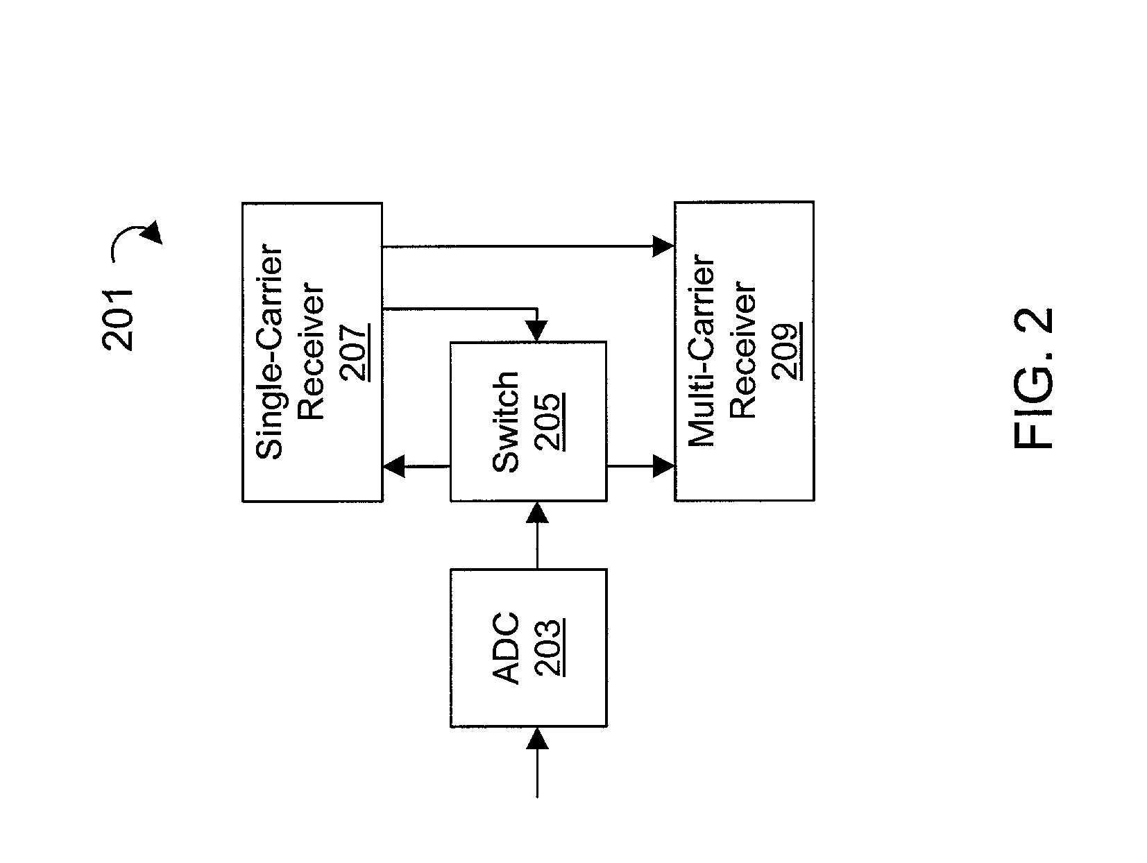
[0044] A configuration according to the present invention reuses the equalizer information obtained during acquisition of the single-carrier portion of the signal. In this manner, no OFDM preamble is required, although it still may be present for both convenience and fine tuning. The present disclosure describes a technique for providing complete continuity between the single-carrier and OFDM (multi-carrier) segments. This continuity is provided by specifying the transmit waveform completely for both the single-carrier and OFDM segments and specifying the transition. This enables complete continuity between the two signal segments, including AGC (power), carrier phase, carrier frequency, timing and spectrum (multi-path). In this manner, the signal does not have to be reacquired by the multi-path portion of the receiver since the information developed during the single-carrier portion (preamble / header) is valid and used to initiate capture of the multi-carrier portion. Maintaining an...


PUM


Abstract

A mixed waveform configuration for wireless communications including a first portion that is modulated according to a single-carrier modulation scheme and a second portion that is modulated according to a multi-carrier modulation scheme. The waveform is specified so that a channel impulse response (CIR) estimate obtainable from the first portion is reusable for acquisition of the second portion. The first portion includes a preamble and header and the second portion typically incorporates the payload.

Description

CROSS-REFERENCE TO RELATED APPLICATION(S)[0001] The present application is based on U.S. Provisional Patent Application entitled "Mixed Waveform Configuration For Wireless Communications", Serial No. 60 / 303,444, filed Jul. 6, 2001, which is hereby incorporated by reference in its entirety.[0002] The present invention relates to wireless communications, and more particularly to a single-carrier to multi-carrier mixed signal configuration for use in wireless communications.[0003] The Institute of Electrical and Electronics Engineers, Inc. (IEEE) 802.11 standard is a family of standards for wireless local area networks (WLAN) in the unlicensed 2.4 and 5 Gigahertz (GHz) bands. The current 802.11b standard defines various data rates in the 2.4 GHz band, including data rates of 1, 2, 5.5 and 11 Megabits per second (Mbps). The 802.11b standard uses direct sequence spread spectrum (DSSS) with a chip rate of 11 Megahertz (MHz), which is a serial modulation technique. The 802.11a standard def...

Claims


Application Information

Patent Timeline
IPC IPC(8): H04J9/00H04J1/02H04J11/00H04L12/28H04L12/56H04L25/02
CPCH04L25/0212H04L25/03006H04L27/0008H04W84/12H04L27/34H04L2025/03401H04L2025/03414H04L27/2601
Inventor WEBSTER, MARK A.SEALS, MICHAEL J.
Owner INTELLECTUAL VENTURES I LLC
Learn More