Fast computation of coefficients for a variable delay decision feedback equalizer

a feedback equalizer and variable delay technology, applied in the field of digital communication, can solve the problems of complexity of optimal equalizer coefficient computation, channel also introduces noise into the symbols, interference between a subject symbol and a plurality of symbols, etc., and achieves the reduction of computation complexity, significant reduction of computation period and/or hardware required for dfe coefficient computation, and increase computation speed

Inactive Publication Date: 2007-08-28
AVAGO TECH INT SALES PTE LTD
View PDF5 Cites 54 Cited by
  • Summary
  • Abstract
  • Description
  • Claims
  • Application Information

AI Technical Summary

Benefits of technology

[0024]The method of the present invention is exact and is much faster than any prior technique that may have been employed to compute DFE coefficients for the same channel and DFE filter lengths. Because the method of the present invention relies upon simple structured recursion, the computation period and/

Problems solved by technology

In many communication systems, such as terrestrial based wireless communication systems, satellite based communication systems, cable based communication systems, etc., the channel distorts the transmitted symbols, from the perspective of the receiver, causing interference between a subject symbol and a plurality of symbols surrounding the subject symbol.
The channel also introduces noise into the symbols prior to their receipt.
A critical factor in increasing the effectiveness of these equalizers is the complexity of optimal equalizer coefficient computation.
However, the overall procedures for calculation of the DFE (FBE and FFE) coefficients have the following problems:1. These procedures require the use of nonstructured recursive equations.
These equations are difficult to implement from the perspective of int

Method used


Image

  • Fast computation of coefficients for a variable delay decision feedback equalizer
  • Fast computation of coefficients for a variable delay decision feedback equalizer
  • Fast computation of coefficients for a variable delay decision feedback equalizer

Examples


first embodiment

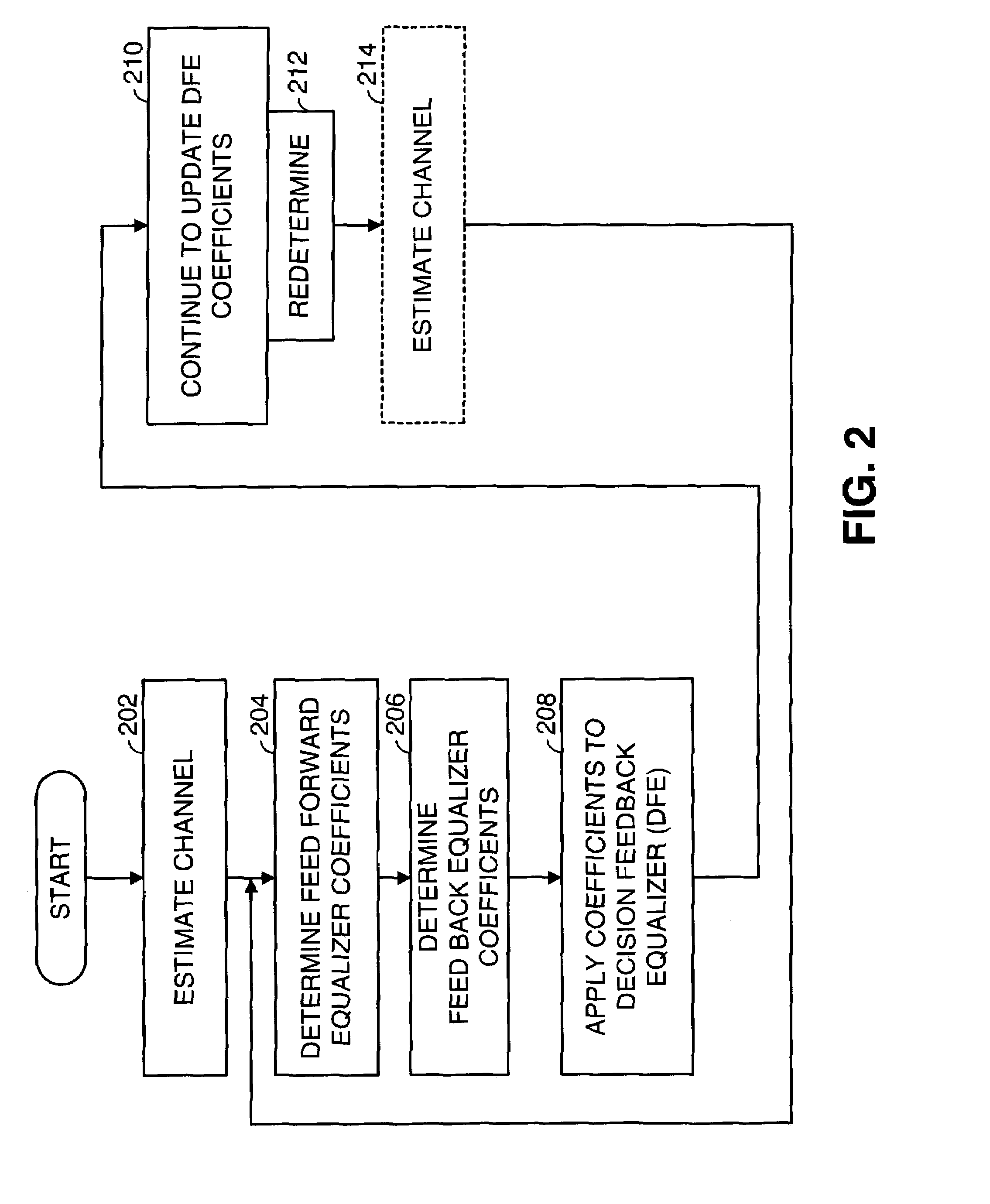
[0159]FIG. 14 is a logic diagram illustrating operation according to the present invention in selecting FBE coefficients. This operation includes first selecting an initial equalizer delay value (step 1402). Then, for the particular equalizer delay value (FBE delay), the operation includes calculating a set of FFE coefficients and FBE coefficients (step 1404). Then operation then includes determining the FBE tap energy for the particular FBE delay (step 1406). If this FBE tap energy is less than a FBE tap energy threshold (as determined at step 1408) the FFE and FBE coefficients determined for the particular FBE are employed (step 1414). If the FBE tap energy is not less than the FBE tap energy threshold (as determined at step 1408), it is next determined whether the FBE delay is at a maximum (step 1410). If so, no acceptable FBE coefficients have been determined for the particular channel response and FBE configuration, the operation has failed (step 1416). However, if the FBE dela...

second embodiment

[0160]FIG. 15 is a logic diagram illustrating operation according to the present invention in selecting FBE coefficients. This operation includes first selecting an initial equalizer delay value (step 1502). Then, for the particular equalizer delay value (FBE delay), the operation includes calculating a set of FFE coefficients and FBE coefficients (step 1504). Then operation then includes determining the FBE tap energy for the particular FBE delay (step 1506). The operation then includes storing the FFE coefficients, the FBE coefficients, and the FBE tap energy along with the particular FBE delay (step 1508). It is next determined whether the FBE delay is at a maximum (step 1510). If so, the FFE coefficients, FBE coefficients, and FBE delay is selected that corresponds to a minimum FBE tap energy (step 1516) of all solutions that have been stored. If the FBE delay is not at the maximum FBE delay (as determined at step 1510), the equalizer delay is increased by a step size (or otherw...


PUM


Abstract

Optimal Decision Feedback Equalizer (DFE) coefficients are determined from a channel estimate by casting the DFE coefficient problem as a standard recursive least squares (RLS) problem and solving the RLS problem. In one embodiment, a fast recursive method, e.g., fast transversal filter (FTF) technique, is used to compute the Kalman gain of the RLS problem, which is then directly used to compute MIMO Feed Forward Equalizer (FFE) coefficients. The FBE coefficients are computed by convolving the FFE coefficients with the channel impulse response. Complexity of a conventional FTF algorithm may be reduced to one third of its original complexity by selecting a DFE delay to force the FTF algorithm to use a lower triangular matrix. The length of the DFE may be selected to minimize the tap energy in the FBE coefficients or to ensure that the tap energy in the FBE coefficients meets a threshold.

Description

CROSS REFERENCES TO RELATED APPLICATIONS[0001]This application is a continuation-in-part of U.S. Regular Utility Application Ser. No. 10 / 154,947, filed May 24, 2002, now U.S Pat. No. 7,113,540, which claims priority to U.S. Provisional Application Ser. No. 60 / 339,253, filed Oct. 26, 2001 and which is a continuation-in-part of U.S. Regular Utility Application Ser. No. 10 / 044,013, filed Oct. 26, 2001, now U.S. Pat. No. 7,027,504, which claims priority to U.S. Provisional Application Ser. No. 60 / 322,994, filed Sep. 18, 2001. This application claims priority to each of these applications and incorporates herein each of these references in its entirety for all purposes.FIELD OF THE INVENTION[0002]This invention relates generally to digital communications; and more particularly to decision feedback based equalizers that are employed in digital communication systems.BACKGROUND OF THE INVENTION[0003]The structure and operation of communication systems is generally known. Many communication ...

Claims


Application Information

Patent Timeline
IPC IPC(8): H03H7/30H03H7/40H03K5/159H04L1/06H04L25/03
CPCH04L1/06H04L25/03057H04L2025/0349H04L2025/03605
Inventor YOUSEF, NABIL R.
Owner AVAGO TECH INT SALES PTE LTD
Why Eureka
Try Eureka