
Robot cleaner, robot cleaning system and method for controlling the same

a robot cleaning and robot technology, applied in the direction of programme control, distance measurement, instruments, etc., can solve the problems of robot cleaner deviating from the planned driving path, generating errors between driving distance and position, and accumulating more position recognition errors, so as to achieve efficient commanding work

Inactive Publication Date: 2005-03-15
SAMSUNG GWANGJU ELECTRONICS CO LTD
View PDF6 Cites 110 Cited by
  • Summary
  • Abstract
  • Description
  • Claims
  • Application Information

AI Technical Summary

Benefits of technology

An object of the invention is to solve at least the above problems and / or disadvantages and to provide a robot cleaner, robot cleaning system and method for controlling the same capable of efficiently performing commanded work by precisely recognizing the driving distance and direction of the robot cleaner.
Preferably, the robot cleaner further comprises an illuminator disposed on the bottom portion of the main body for illuminating an area photographed by the downward-looking camera so as to render it brighter than surrounding areas.
With the above described robot cleaner, robot cleaning system and method for controlling the same, the driving distance and direction of the robot cleaner are recognized by using the images of the floor photographed by the downward camera to arrange the driving path, thereby capable of efficiently performing the commanded work.

Problems solved by technology

However, the above generally used method for driving the robot cleaner along the driving path may produce errors between the driving distance and position calculated from the signal detected by the sensor and the actual driving distance and position due to an irregularity of the floor, slip of the wheels, etc.
The more distance over which the robot cleaner drives, the more the position recognition errors may be accumulated.
The accumulated position errors may accordingly cause the robot cleaner to deviate from the planned driving path.
Consequently, cleaning may not be performed for some of the predetermined area, or may be repeatedly performed for other areas, whereby cleaning efficiency can diminish and security work may not be performed in some cases.

Method used


Image

  • Robot cleaner, robot cleaning system and method for controlling the same
  • Robot cleaner, robot cleaning system and method for controlling the same
  • Robot cleaner, robot cleaning system and method for controlling the same

Examples


Embodiment Construction

The preferred embodiments of the invention will be hereinafter described in detail with reference to the accompanying drawings.

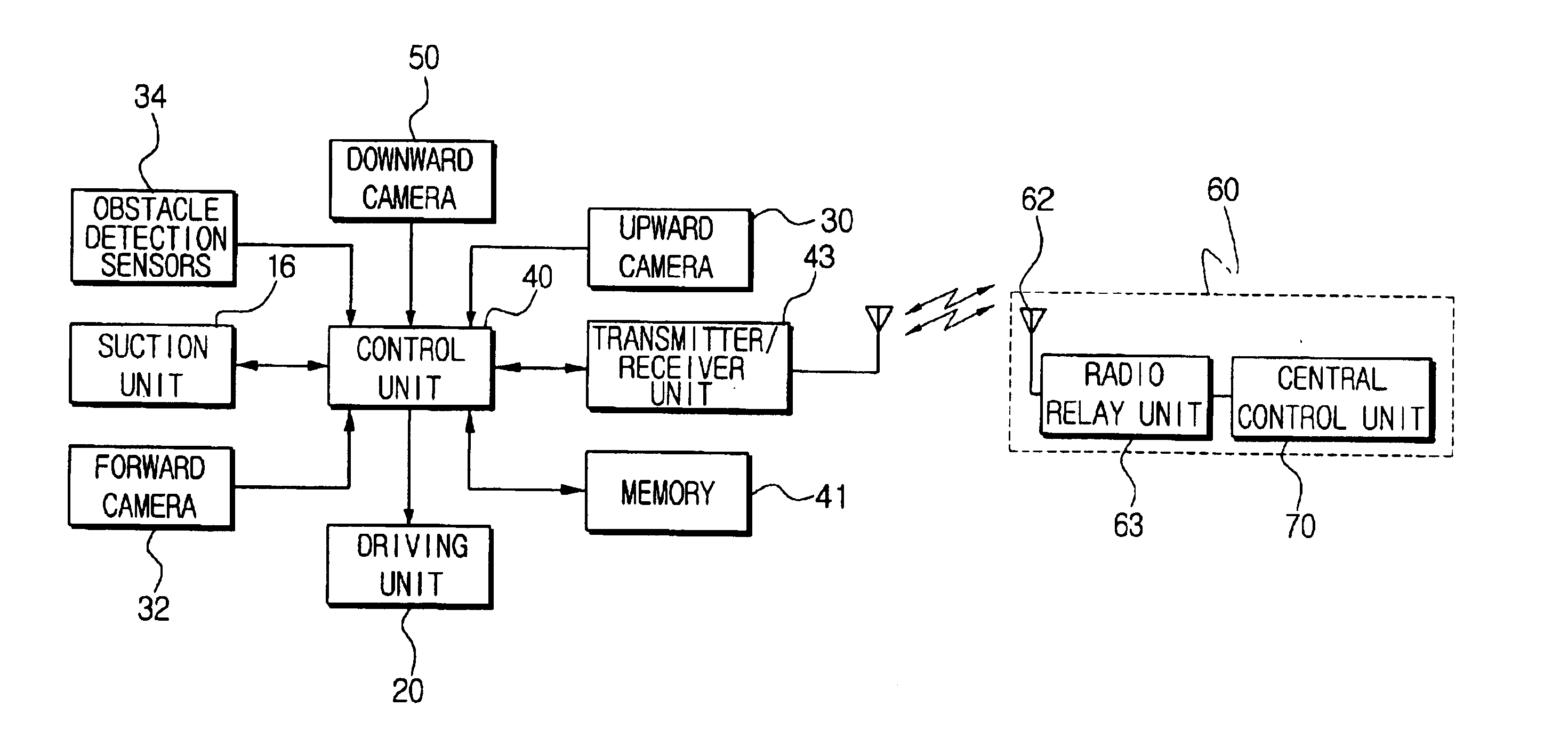
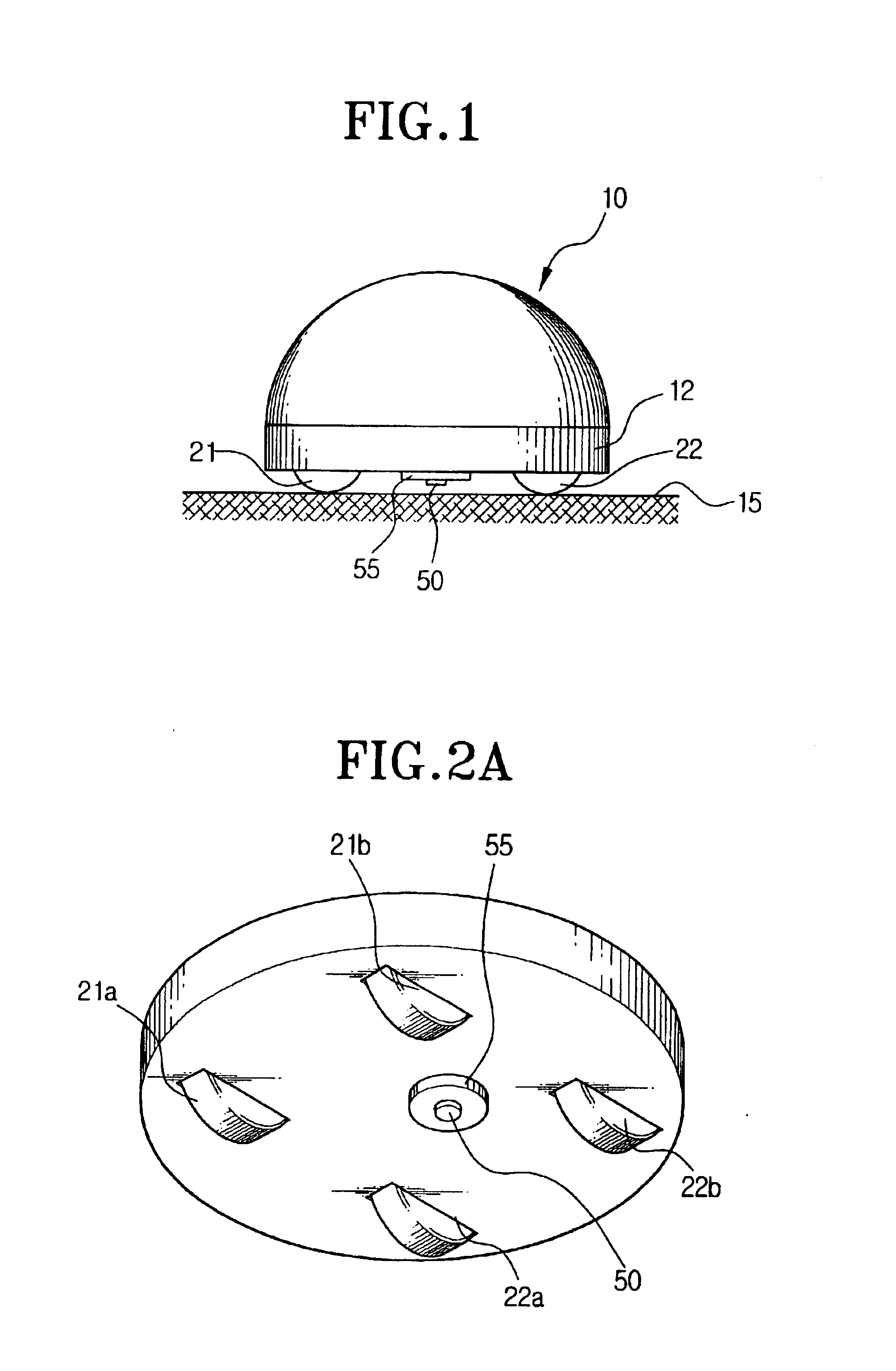
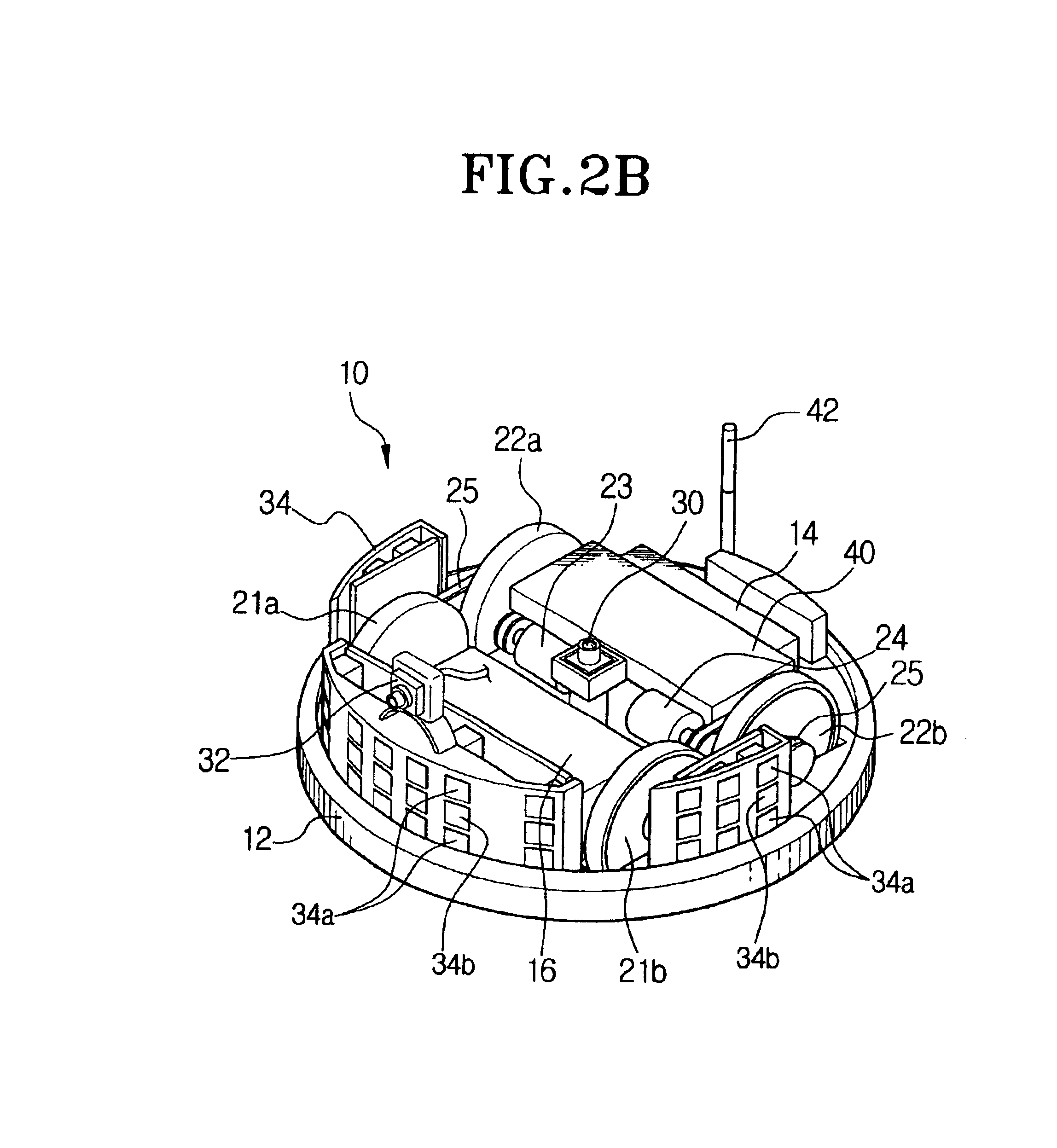
Referring to FIGS. 1, 2A and 2B, a robot cleaner 10 is provided with a main body 12, a suction unit 16, a driving unit 20, an upward-looking camera 30, a forward-looking camera 32, obstacle detection sensors 34, a downward-looking camera 50, an illuminator 55, a control unit 40, a memory 41 and a transmitter / receiver unit 43. The power source may comprise a stored electrical source, such as battery 14.

The suction unit 16 is installed on the main body 12 in order to collect dust on a surface, such as a floor, to be cleaned while drawing in air. The suction unit 16 can be constructed using well-known methods. The suction unit 16, as an example, may have a suction motor (not shown), and a suction chamber, for collecting dust drawn in through a suction hole or a suction pipe formed on, for example, the underside of the body 12, opposite to the floor to be cleane...


PUM


Abstract

A robot cleaner, a robot cleaning system and a method for controlling the same capable of efficiently performing work on command by recognizing the driving distance and direction of the robot cleaner regardless of a of wheel slippage or irregularity in the floor. The robot cleaner performs a working operation while moving about a floor, and comprises a main body, a driving unit for driving a plurality of wheels disposed on a bottom portion of the main body, a downward-looking camera disposed among the wheels on the bottom portion of the main body for photographing images of the floor perpendicular to the driving direction of the robot cleaner, and a control unit for recognizing driving distance and direction of the wheels using image information of the floor photographed by the downward-looking camera, and for controlling the driving unit corresponding to a target work by using the recognized distance and direction of the wheels. An upward-looking camera can photograph and use information relating to spatial orientation for determining and correcting driving distance and direction.

Description

BACKGROUND OF THE INVENTION1. Field of the InventionThe present invention relates generally to a robot cleaner, a robot cleaning system and a method for controlling the same, and more particularly to a robot cleaner, a robot cleaning system and a method for controlling the same that is capable of recognizing driving distance and direction to arrange a driving path by using image information of a floor photographed while the robot cleaner is driving around the floor.2. Background of the Related ArtA conventional robot cleaner drives along an outline of a work area that is surrounded by a wall or obstacle by using an ultrasonic sensor installed in a main body to determine the extent of the work area, and then plans a driving path for its work, such as cleaning or security work, in the predetermined work area. The robot cleaner, then, calculates driving distance and current position by using a signal detected by a sensor such as an encoder capable of detecting a number and angle of rot...

Claims


Application Information

Patent Timeline
Patent Type & Authority Patents(United States)
IPC IPC(8): A47L9/30A47L9/00G05D1/02A47L9/28
CPCA47L9/009A47L9/2805A47L9/2852A47L9/2857A47L9/30G05D1/0246G05D1/0282A47L9/2894A47L2201/04G05D2201/0215A47L9/28
Inventor SONG, JEONG-GONHWANG, YUN-SUP
Owner SAMSUNG GWANGJU ELECTRONICS CO LTD
Learn More