Blind fastener and nose assembly for installation of the blind fastener

a technology of blind fasteners and nose assemblies, which is applied in the direction of threaded fasteners, load modified fasteners, screwed fasteners, etc., can solve the problems of wear damage to the nose nibs, the operation of the blind side bulb not being effective enough to clamp a plurality of workpieces together, and the bushing is wet, so as to reduce the wall thickness, facilitate the threading, and reduce the effect of wall thickness

Inactive Publication Date: 2005-03-22
HUCK INT INC
View PDF31 Cites 62 Cited by
  • Summary
  • Abstract
  • Description
  • Claims
  • Application Information

AI Technical Summary

Benefits of technology

Certain objects of the invention are obtained by providing a blind fastener for securing a plurality of workpieces together. The workpieces have an accessible side workpiece and a blind side workpiece. The blind fastener has a sleeve with a body that is internally threaded at one end of the sleeve and a head at the other end of the sleeve. The threaded portion of the sleeve is adjacent to an internally smooth portion of the sleeve. The threaded portion of the sleeve transitions to the smooth portion of the sleeve, and the smooth portion of the sleeve has a reduced wall thickness relative to the threaded portion of the sleeve. The head has a plurality of rearwardly sloping recesses disposed in the head of the sleeve that are adapted to be engaged with a plurality of rearwardly sloping nibs disposed on one end of a nose secured to an installation tool. The recesses are relatively shallow. The blind fastener additionally has a pin member with an elongated shank. The shank has a straight smooth portion received within the smooth portion of the sleeve and a threaded portion at one end of the pin member that is threadedly engaged with the threaded portion of the sleeve. The pin member has a first head adjacent to the shank that is seated within the sleeve and a second splined head positioned at the other end of the pin member. The pin member has a breakneck groove between the first head and the second head. The breakneck groove is adapted to fracture in torsional shear in response to a relative rotational force applied to the fastener with an installation tool that facilitates threading of the threads of the pin member with the threads of the

Problems solved by technology

Unfortunately, the use of deep recesses would weaken the bushing.
Such an operation would not effectively form the blind side bulb to clamp a plurality of workpieces together because the nibs of the nose would cam-out of the recesses during the installation of this prior art fastener.
When the nibs cam-out of the recesses, the bushing rotates relative to the nose thereby causing wear damage to the nibs of the nose due to the abrasion of the nibs rotating against the head of the bushing.
Additionally, the rotation of the bushing relative to the screw is undesirable from the standpoint of forming the blind side bulb.
Optimum

Method used


Image

  • Blind fastener and nose assembly for installation of the blind fastener
  • Blind fastener and nose assembly for installation of the blind fastener
  • Blind fastener and nose assembly for installation of the blind fastener

Examples


Embodiment Construction

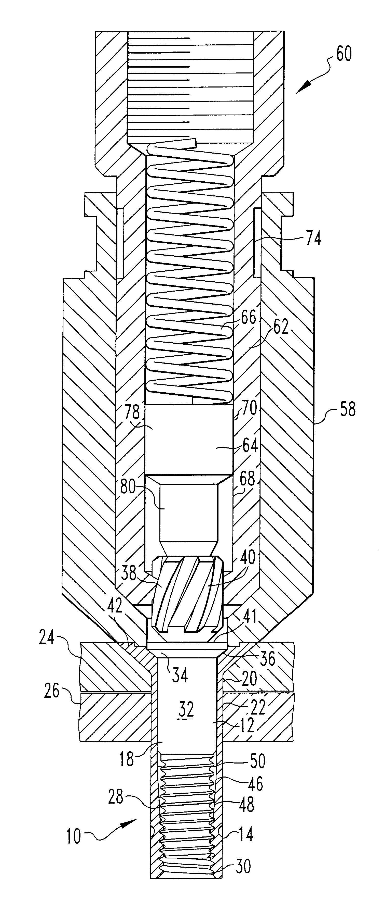
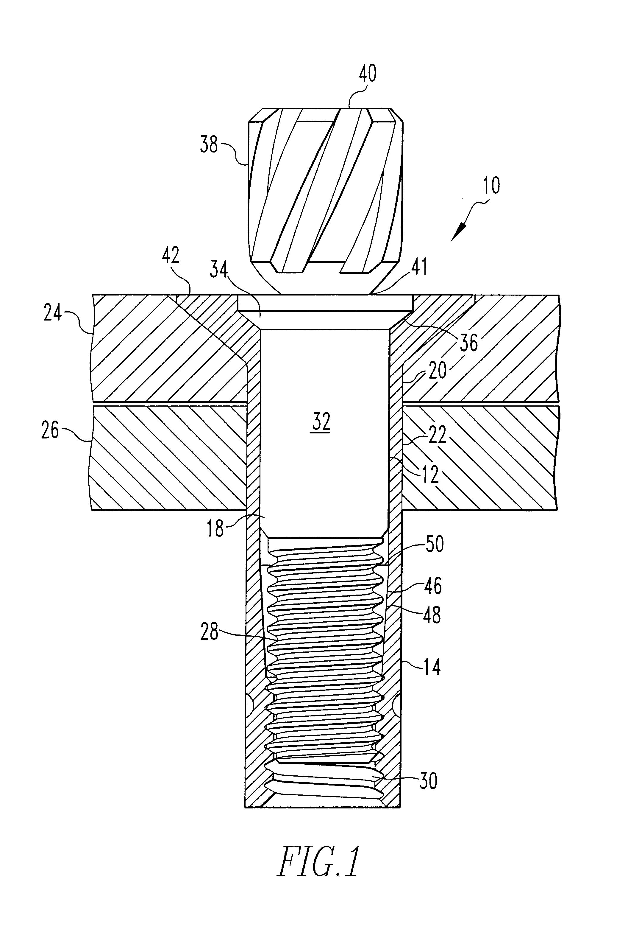
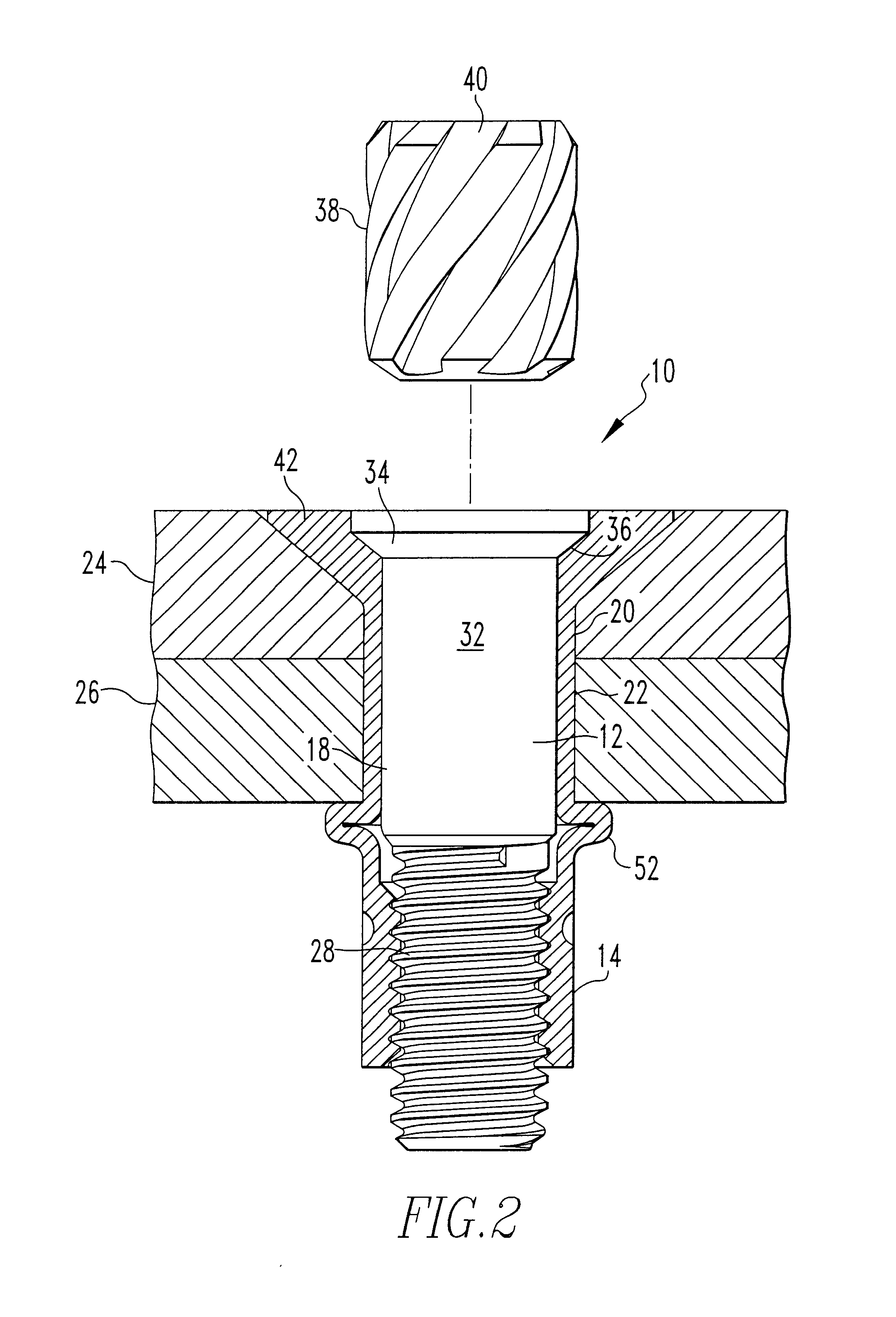
Looking now to FIG. 1, a fastener 10 is shown to include a pin member 12 and a sleeve 14. In the fastener industry, pin member 12 may be referred to as a bolt, a screw, a spindle or a stem and sleeve 14 may be referred to as a bushing, nut or nut body. Pin member 12 has an elongated shank 18 which extends through aligned openings 20 and 22 in a pair of workpieces 24 and 26, respectively, to be secured together. A threaded portion 28 at one end of shank 18 is adapted to threadedly engage an internally threaded portion 30 of the sleeve 14 that is an integral component of the sleeve 14. The threaded portion 28 of the shank 18 has a diameter that is less than a smooth portion 32 of the shank 18 adjacent to the threaded portion 28. The pin member 12 is provided with a head 34 adjacent to the smooth portion 32 that is adapted to seat on an annular, outwardly facing, seat 36 at the outer end of the sleeve 14. In the particular construction illustrated, the head 34 is frustoconical and the ...


PUM


Abstract

A blind fastener for securing a plurality of workpieces is provided that has a sleeve, and a pin member. In an alternate embodiment, the blind fastener has a sleeve, a pin member and a nut. The sleeves have a head with a plurality of rearwardly sloping recesses disposed therein. The recesses are adapted to be engaged with a plurality of rearwardly sloping nibs disposed on one end of a nose secured to an installation tool. The pin members have a splined head adapted to be engaged with a splined driver secured to an installation tool. Use of the splined head on the pin member, the splined driver, rearwardly sloping recesses on the sleeve, and rearwardly sloping nibs on the nose eliminates camming out of the nibs from the recesses during installation of the blind fastener. A nose assembly for installation of the blind fastener is also provided.

Description

FIELD OF THE INVENTIONThis invention relates to blind fasteners for securing workpieces together, and more particularly to a blind fastener and nose assembly for installation of the blind fastener.BACKGROUND OF THE INVENTIONBlind fasteners are commonly used to secure workpieces together when it is otherwise impossible to access the blind side of one of the workpieces. Typically, the workpiece that is accessible by an end-user is referred to as the accessible side workpiece and the workpiece that is inaccessible by an end-user is referred to as the blind side workpiece.Blind fasteners have wide application in the aerospace industry. In aerospace applications, the blind fastener assembly of the present invention can be used to secure workpieces made of aluminum alloy, other metallic alloys, composites or combinations thereof.An example of a previously available blind fastener is disclosed in U.S. Pat. No. 2,971,425. The principle components of the blind fastener of this prior art pate...

Claims


Application Information

Patent Timeline
IPC IPC(8): B25B27/00B25B23/14F16B19/04F16B31/00F16B19/10F16B31/02F16B23/00
CPCB25B23/1415B25B27/0007F16B31/021F16B19/1072F16B23/0061F16B19/1054B25B27/0014
Inventor HUFNAGL, GERHARTLEE, GILBERT M.TORRENCE, RANDALL G.
Owner HUCK INT INC
Why Eureka
Try Eureka