
Single stage kinetic energy warhead utilizing a barrier-breaching projectile followed by a target-defeating explosively formed projectile

a kinetic energy warhead and barrier-breaching technology, applied in the field of ballistics, can solve the problems of requiring time for planning and execution, affecting the safety of personnel, and blocking primary targets,

Inactive Publication Date: 2005-03-22
UNITED STATES OF AMERICA THE AS REPRESENTED BY THE SEC OF THE ARMY
View PDF4 Cites 14 Cited by
  • Summary
  • Abstract
  • Description
  • Claims
  • Application Information

AI Technical Summary

Benefits of technology

The weight and volume of the stacked liner configuration of the present system is significantly lower than the weight and volume of current systems. The single stage kinetic energy warhead requires a single firing explosive train eliminating developmental cost and complex fusing. The single stage kinetic energy warhead utilizes explosive detonation, simplifying the delivery of a projectile and eliminating the need for a missile delivery system. The size and simplicity of the single stage kinetic energy warhead allows for portability and use by an individual.
In a further embodiment, the front liner and the main liner comprise copper. In yet another further embodiment, the front liner and the main liner comprise silver. These more ductile materials (copper and silver) allow the shockwave to create a barrier-breaching projectile with a diameter larger than the diameter of the front liner. In further embodiments, the front liner and the main liner comprise different shapes and configurations, allowing for varying projectile lengths.

Problems solved by technology

In tactical military exercises, primary targets are often blocked by intermediate barriers or obstacles.
However, manual labor operations expose military personnel to harm and require time for planning and execution.
However, these systems require multiple and complex explosive firing trains, are expensive, require a missile delivery system for deployment, and cannot typically be transported or deployed by an individual because of their size and weight.
After detonation, the explosive products create enormous pressures that accelerate one or more liners while simultaneously reshaping the liners into a rod or some other desired shape.
The need for such a system has heretofore remained unsatisfied.

Method used


Image

  • Single stage kinetic energy warhead utilizing a barrier-breaching projectile followed by a target-defeating explosively formed projectile
  • Single stage kinetic energy warhead utilizing a barrier-breaching projectile followed by a target-defeating explosively formed projectile
  • Single stage kinetic energy warhead utilizing a barrier-breaching projectile followed by a target-defeating explosively formed projectile

Examples


Embodiment Construction

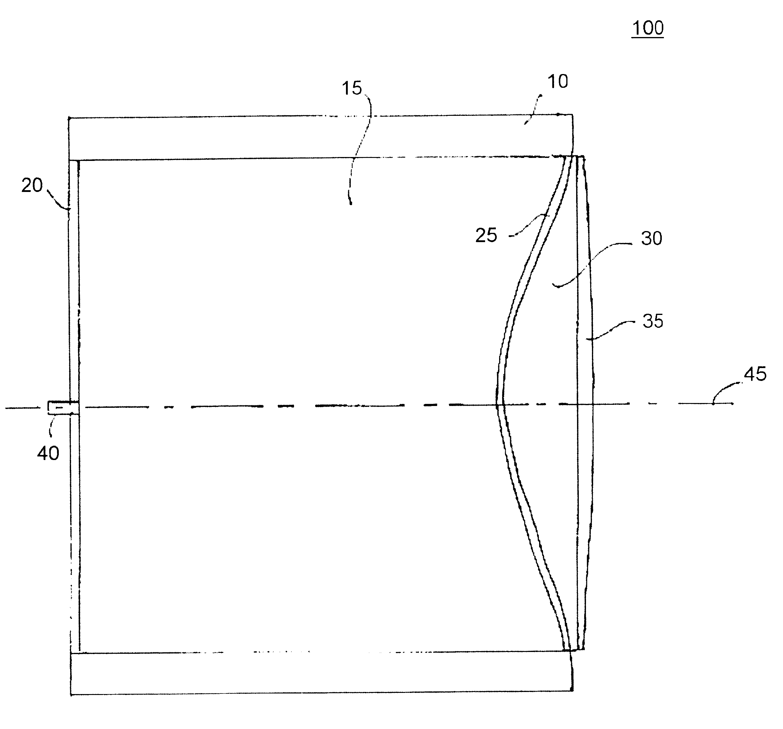
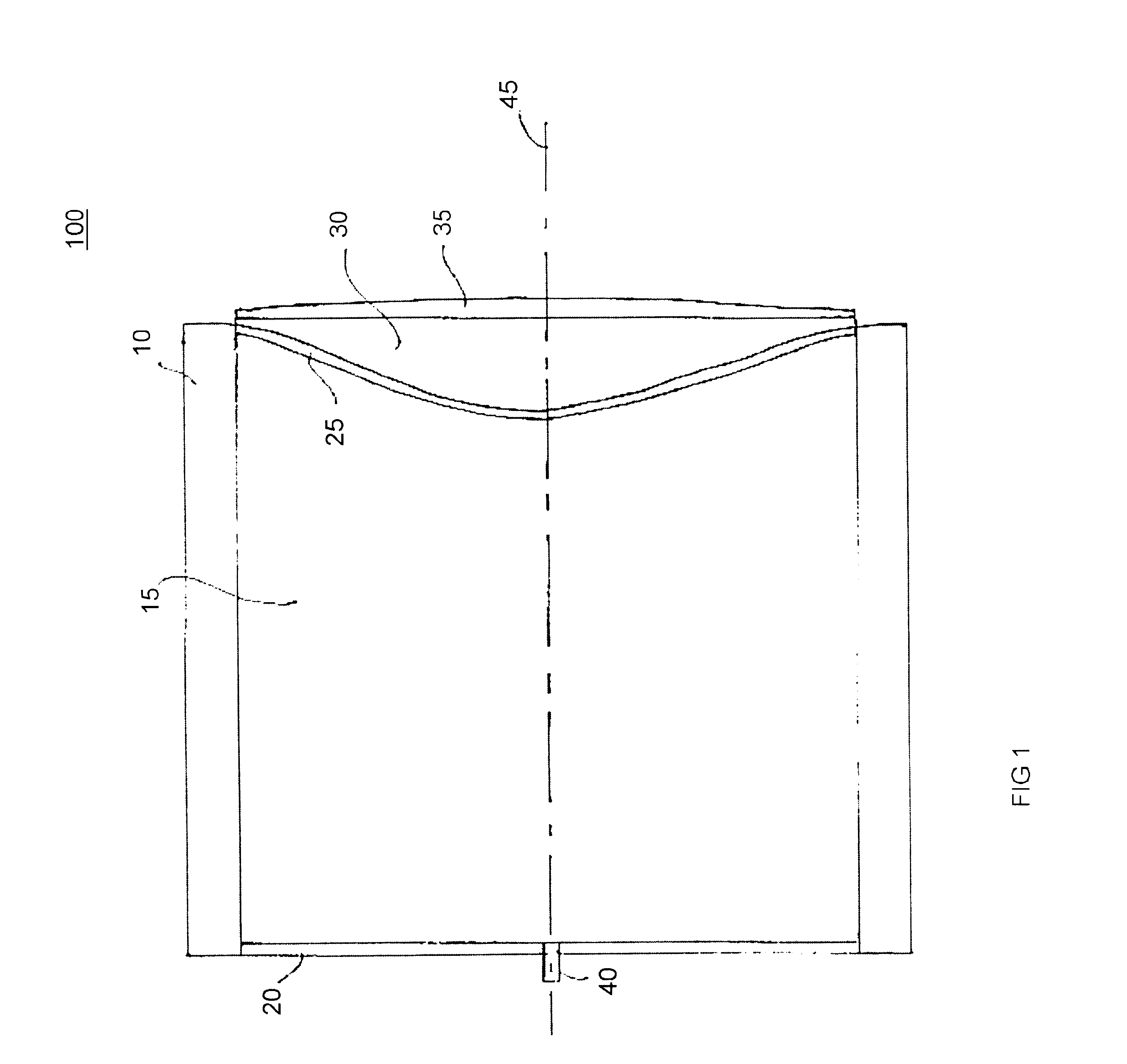
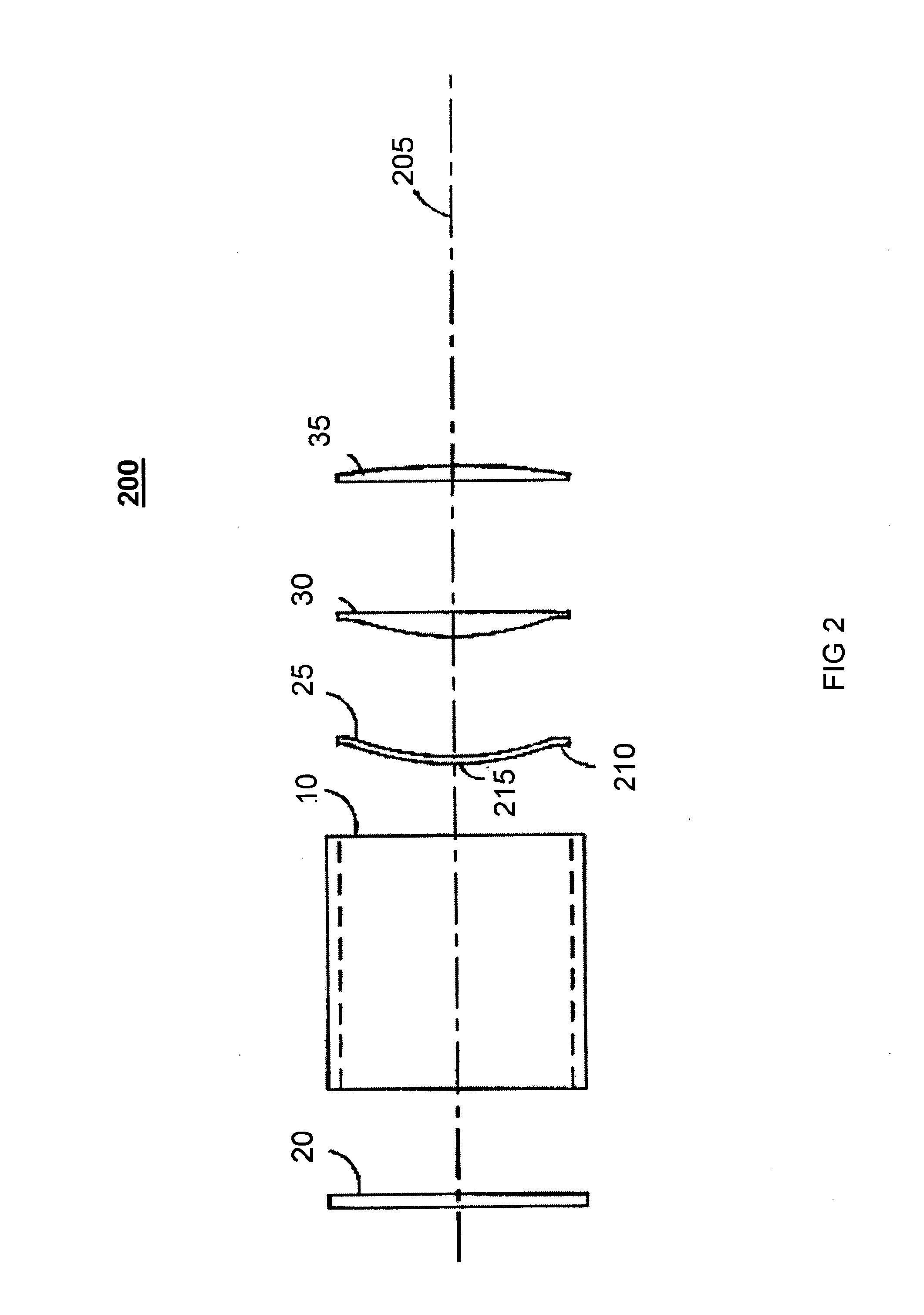
FIGS. 1 and 2 illustrate an exemplary embodiment of a single stage kinetic energy warhead 100 utilizing a barrier-breaching projectile followed by a target-defeating explosively formed projectile (also referenced herein as warhead 100) according to the present invention. Warhead 100 comprises a metal housing 10, a main explosive charge 15, a back plate 20, a main liner 25, a foam insert 30, a front liner 35, and a detonator assembly 40. Warhead 100 is cylindrical with respect to axis 45. The projectile assembly 200 of warhead 100 is illustrated by the diagram of FIG. 2. The projectile assembly 200 generally comprises metal housing 10, the back plate 20, the main liner 25, the foam insert 30, and the front liner 35 assembled along a central axis 205.

The back plate 20 and the metal housing 10 provide a protective casing for the main explosive charge 15 and the main liner 25. In addition, the mass of the metal housing 10 provides confinement for the main explosive charge 15. The additi...


PUM


Abstract

A single stage kinetic energy warhead using multiple explosively formed projectile (EFP) liners in a stacked configuration is capable of breaching intermediate barriers and defeating a primary target. The main explosive charge is detonated and the subsequent shockwave causes the front liner to be shaped to breach an intermediate barrier. The main liner is formed into a more compact rod-shaped projectile designed to defeat the main target. The weight and volume of the stacked liner configuration of the present system is significantly lower than the weight and volume of current systems. The present system requires a single firing explosive train eliminating developmental cost and complex fusing. The present system utilizes explosive detonation, simplifying the delivery of a projectile and eliminating the need for a missile delivery system. The size and simplicity of the present system allows for portability and use by an individual.

Description

BACKGROUND OF INVENTION1. Field of the InventionThe present invention generally relates to the field of ballistics and in particular to explosively formed projectiles. More specifically, the present invention relates to an explosively formed barrier-breaching plate for clearing barriers in advance of an explosively formed projectile.2. Background of the InventionIn tactical military exercises, primary targets are often blocked by intermediate barriers or obstacles. These obstacles can be fences, covers, forestry, or light armor. The intermediate barriers or obstacles can be breached by a preliminary manual labor operation. However, manual labor operations expose military personnel to harm and require time for planning and execution. As an alternative, the intermediate barriers or obstacles can be breached by current warhead systems comprising multiple warheads within a single envelope. However, these systems require multiple and complex explosive firing trains, are expensive, requir...

Claims


Application Information

Patent Timeline
IPC IPC(8): F42B1/00F42B1/02F42B12/02F42B12/10F42B12/16
CPCF42B1/02F42B12/16F42B12/10
Inventor THOMPSON, LAMARNG, WILLIAMFONG, RICHARD
Owner UNITED STATES OF AMERICA THE AS REPRESENTED BY THE SEC OF THE ARMY
Learn More