Method for controlling the damper current for an electrically adjustable damper

Inactive Publication Date: 2005-03-22
CONTINENTAL AG
View PDF12 Cites 4 Cited by
  • Summary
  • Abstract
  • Description
  • Claims
  • Application Information

AI Technical Summary

Benefits of technology

The advantage of the invention is that disturbing noises in the motor vehicle, which are caused by an intense jump-like change of the damper current of an electrically adjustable damper, can be reduced and / or suppressed. A further advantage of the invention is that, for this reduction or suppression, no additional components such as mufflers, et cetera or changes of existing components are necessary. A further advantage of the invention is that the control of the electrically adjustable damping force is possible in an unlimited manner via the current within specific pregiven limits.
is that disturbing noises in the motor vehicle, which are caused by an intense jump-like change of the damper current of an electrically adjustable damper, can be reduced and / or suppressed. A further advantage of the invention is that, for this reduction or suppression, no additional components such as mufflers, et cetera or changes of existing components are necessary. A further advantage of the invention is that the control of the electrically adjustable damping force is possible in an unlimited manner via the current within specific pregiven limits.
According to another feature of the invention, for a 
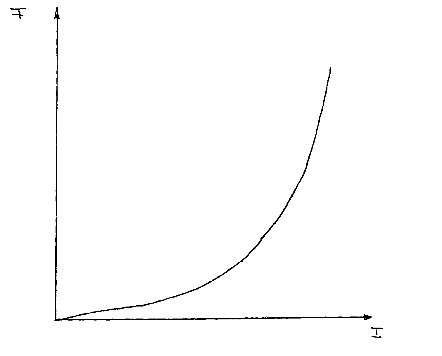
positive current change (that is, for an adjustment of the current to higher current values, which effect a greater damping force), a different limit for the adjustment per time interval is pregiven than for a negative current change (that is, the adjustment of the current to lower current values and therefore the adjustment of the damping force to lower force values). The advantage of this embodiment becomes manifest when one considers that the current / damping-force characteristic line does not run linearly. Rather, for some typical electrical dampers, the current / damping-force characteristic line runs progressively. If, in this case, a lower limit is pregiven for the positive current change per time interval than for the negative current change per time interval, the progressive trace of the current / damping-force characteristic line can be compensated; that is, the jumps in the damper force can be selected to have approximately the same magnitude independently of the direction in which the current is to be changed.
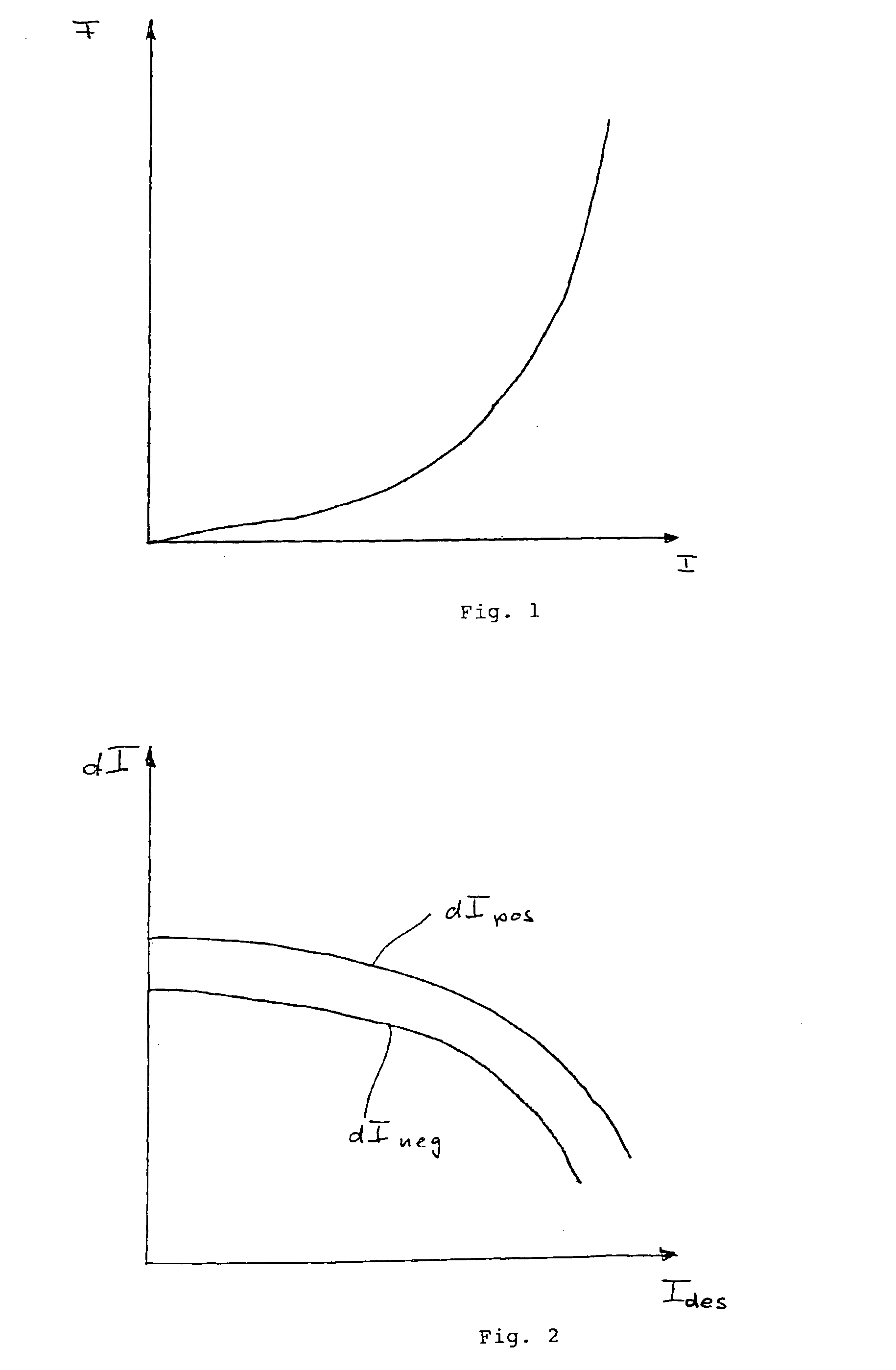
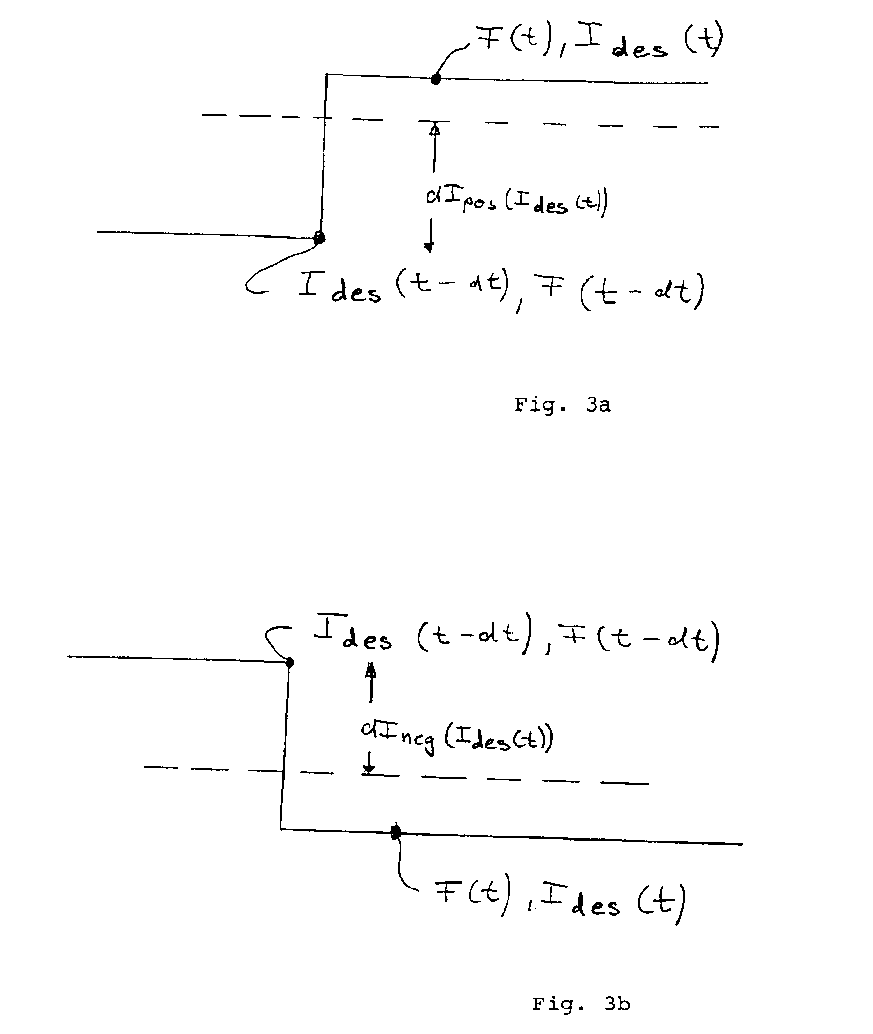
According to another feature of the invention, the limit per time interval for the positive current change as well as the limit for the current change per time interval for the negative current change is pregiven in dependence upon the desired current to which the control is to be made. The advantage of this embodiment is that an additional possibility is provided to preset the limits for the current change in dependence upon the current / damping-force characteristic line and to adapt the limits to this characteristic line.
According to a further embodiment of the invention, the limit of the permissible current change per time interval for the positive current change as well as for the negative current change is preset as a function of the speed of the bodywork of the motor vehicle (that is, the relative speed of the bodywork of the motor vehicle to the wheel of the motor vehicle in the region of the particular damper). This embodiment is especially advantageous when applying the skyhook control method because, in this control method, the damping force requirement is derived from the bodywork speed and, in the simplest case, utilizing a proportional member. In this case, a low damping force request is adjusted for low bodywork speeds and a high damping force request is adjusted for high bodywork speeds. Especially for low damping force speeds, large current jumps are avoided because of the method of the invention in that for low bodywork speeds, the permissible current change is greatly limited.
According to another embodiment of the invention, the duration of the time intervals within which a specific current change is permitted (which is restricted by the limits) lies in the range of 1 ms to 50 ms, preferably, in the range of 15 to 25 ms.

Problems solved by technology

However, it has been shown that jumps in the damping force can cause unwanted noises in the motor vehicle.

Method used


Image

  • Method for controlling the damper current for an electrically adjustable damper
  • Method for controlling the damper current for an electrically adjustable damper
  • Method for controlling the damper current for an electrically adjustable damper

Examples


Embodiment Construction

FIG. 1 shows, by way of example, a current / damping-force characteristic line for an electrically adjustable damper of a motor vehicle for a specific bodywork speed (a separate current / damping-force characteristic line corresponds to each bodywork speed of the motor vehicle and such a characteristic line is correspondingly stored in the control unit of the motor vehicle).

The damper of the motor vehicle is controlled as described below.

The damping force F has a specific value which is adjusted via a specific electrical current at the damper. The electronics of the motor vehicle detect that the instantaneous damping force must be adapted (for example, increased) because of the driving situation of the motor vehicle. From the characteristic line, the new current to be adjusted is determined and is correspondingly adjusted at the damper so that the desired damping force is present after the adjustment at the damper. Here, it has been shown that, because of specific current jumps, jumps i...


PUM


Abstract

A method controls the damper current of a damper of a motor vehicle. The damper is adjustable by an electrical current and the permissible change of the current per time interval is delimited by a limit.

Description

FIELD OF THE INVENTIONThe invention relates to a method for controlling the damper current of an electrically adjustable damper of a motor vehicle. With dampers of this kind, the vibrations of the vehicle bodywork relative to the wheels of the motor vehicle are damped.BACKGROUND OF THE INVENTIONElectrically adjustable dampers are known from the state of the art. In these electrically adjustable dampers, the damper desired force can be adjusted with the aid of a controllable electrical current in dependence upon the driving situation of the motor vehicle in which the damper is mounted. Here, the current is controlled with the aid of a current / damping-force characteristic line, wherein a specific damping force is pregiven in dependence upon the vehicle situation and, from this characteristic line, it is determined which current is to be adjusted in order to adjust the pregiven damping force. This method of controlling electrically adjustable dampers is also utilized in the skyhook con...

Claims


Application Information

Patent Timeline
IPC IPC(8): B60G17/08B60G17/06F16F9/46F16F9/44
CPCB60G17/08F16F9/46B60G2202/414B60G2400/5182B60G2400/60B60G2500/10B60G2600/02B60G2600/184B60G2600/44B60G2600/85B60G2800/162B60G2500/114
Inventor KOCK, JORGJOHANNKNECHT, RALFGROTENDORST, JORGZOUFAL, STEFANSTILLER, ALEXANDERHOINKHAUS, HERMANN
Owner CONTINENTAL AG
Why Eureka
Try Eureka