Developing apparatus and developing method

a technology of developing apparatus and developing method, which is applied in the direction of coating, instruments, photosensitive materials, etc., can solve the problems of increasing the size of the substrate, the amount and velocity of the rinsing liquid supply the inability to uniformly supply the rinsing liquid along the discharge width of the discharge unit, so as to reduce the amount of projection of the tip portion, increase the size of the tray, and improve the uniformity

Inactive Publication Date: 2005-03-22
SOKUDO CO LTD
View PDF9 Cites 25 Cited by
  • Summary
  • Abstract
  • Description
  • Claims
  • Application Information

AI Technical Summary

Benefits of technology

Since, with the rotation of the substrate, the rinsing liquid supply nozzle is rotated to pass over the substrate and to supply a rinsing liquid to the major surface of the substrate, the rinsing liquid supply nozzle moves generally along an arc in the form of strip relative to the substrate. This improves uniformity in the supply of a rinsing liquid.
Further, since the rotation axis of the rinsing liquid supply nozzle is relatively far away from the rotation axis of the substrate at least either when the rinsing liquid supply nozzle starts passing over the substrate or when it has finished passing over the substrate, it is possible to reduce the amount of projection of the tip portion of the rinsing liquid supply nozzle from the outer periphery of the substrate. This prevents an increase in the size of a tray for receiving a rinsing liquid.
Thus, an object of the present invention is to improve uniformity in the supply of a rinsing liquid.
Another object of the present invention is to prevent an increase in the size of a tray for receiving a rinsing liquid.

Problems solved by technology

However, in the above developing apparatuses, for reasons such as adhesion of undesirable matter to the discharge units and any possible defects resulting therefrom, the supply of a rinsing liquid from the slit discharge unit may not be uniform (for example, in amount and in velocity) along a discharge width of the discharge unit.
The same can be said of the supply of a developer, but since especially a rinsing liquid needs to be passed over a layer of developer, the spacing between the rinsing liquid supply nozzle and the substrate becomes greater and, as a result, there is a greater likelihood that the supply of a rinsing liquid is not uniform.

Method used


Image

  • Developing apparatus and developing method
  • Developing apparatus and developing method
  • Developing apparatus and developing method

Examples


first preferred embodiment

In this first preferred embodiment, a developing apparatus is described which, while holding a substrate at rest, moves a developer supply nozzle and a rinsing liquid supply nozzle along a line running diagonally relative to a virtual scanning direction of the substrate.

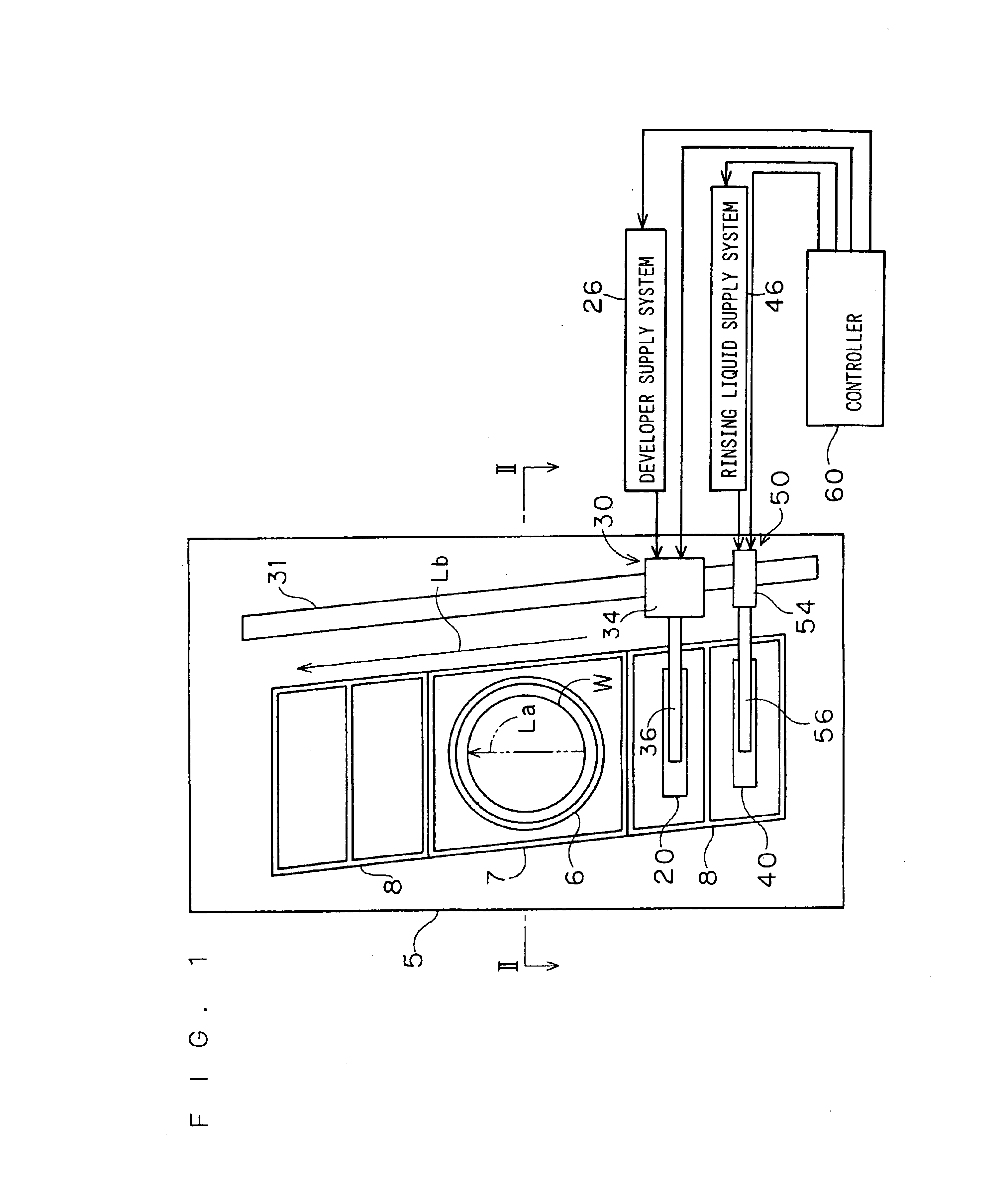
FIG. 1 is a plan view showing a schematic configuration of the developing apparatus according to the first preferred embodiment of the present invention, and FIG. 2 is a cross-sectional view taken along the line II—II of FIG. 1. In FIG. 2, a developer supply nozzle 20 or a rinsing liquid supply nozzle 40 moving over a substrate W is illustrated by the dash-double dot lines.

This developing apparatus is configured to supply a developer and a rinsing liquid as processing liquids to the substrate W after being exposed for development processing. It comprises a substrate holder 10 for holding the substrate W, the developer supply nozzle 20, a first nozzle movement mechanism 30 for moving the developer supply nozzle 20, th...

second preferred embodiment

<A. Description of Developing Apparatus>

In this second preferred embodiment, a developing apparatus is described which, while rotating a substrate, rotates a processing liquid supply nozzle so that the nozzle passes over the substrate.

FIG. 11 is a plan view showing a schematic configuration of the developing apparatus according to the second preferred embodiment of the present invention.

The developing apparatus is configured to supply a developer and a rinsing liquid as processing liquids to the substrate W after being exposed for development processing. It comprises a substrate holder 110 for holding the substrate W, a developer supply nozzle 120, a first nozzle movement mechanism 130 for moving the developer supply nozzle 120, a rinsing liquid supply nozzle 140, a second nozzle movement mechanism 150 which is a rinsing liquid supply nozzle rotating section for rotating the rinsing liquid supply nozzle 140, and a controller 160 for controlling the operation of the entire appar...

third preferred embodiment

<A. Description of Developing Apparatus>

A description will now be made of a developing apparatus according to a third preferred embodiment of the present invention.

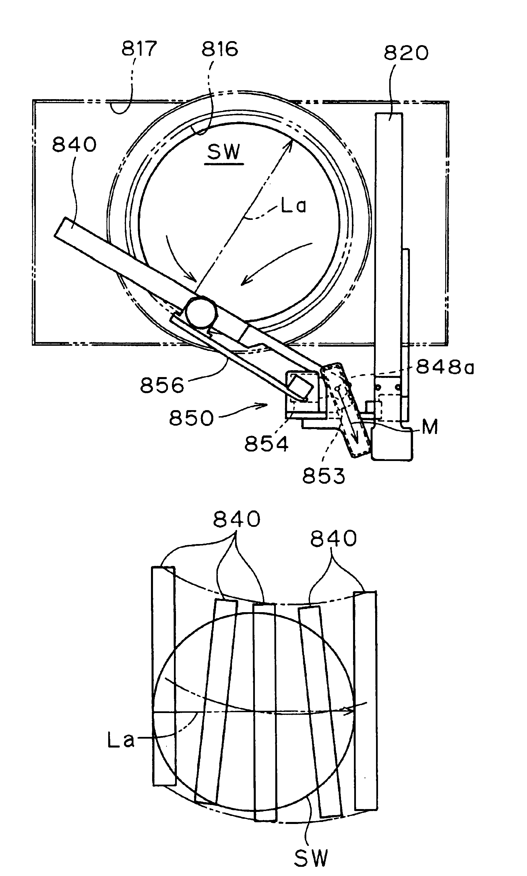
FIGS. 21 and 22, respectively, are plan and side views showing a schematic configuration of the developing apparatus, and FIG. 23 is a cross-sectional view taken along the line XXIII—XXIII of FIG. 21. In FIG. 23, a portion where a substrate is held is also shown in cross section.

This developing apparatus is configured to develop a thin resist film which is formed on the surface of a semiconductor wafer SW as a substrate. Prior to development processing by this apparatus, a predetermined pattern is exposed onto the thin resist film by an exposure apparatus.

More specifically, this developing apparatus may, for example, be disposed as a development unit in a substrate processing apparatus disclosed in U.S. Pat. No. 6,051,101. It is, however, to be understood that the form of installation of the developing apparatus of t...


PUM


Abstract

A substrate (SW) is rotatably held in an approximately horizontal position by a wafer holding and rotation mechanism (810). One end of a rinsing liquid supply nozzle (840) is rotatably supported by a rinsing liquid supply nozzle rotation supporting mechanism (850) to pass over the substrate (SW). In response to rotation of the rinsing liquid supply nozzle (840), the rotation axis of the rinsing liquid supply nozzle (840) moves in a direction closer to or away from the rotation axis of the substrate (SW), whereby the amount of projection of a tip portion of the rinsing liquid supply nozzle (840) is reduced.

Description

BACKGROUND OF THE INVENTION1. Field of the InventionThe present invention relates to a substrate processing apparatus and method for supplying a developer, a rinsing liquid and the like to substrates such as semiconductor wafers and glass substrates for liquid crystal display panels and for plasma display panels. And it relates especially to a developing apparatus and developing method for developing a thin resist film formed on those substrates and having a predetermined pattern exposed.2. Description of the Background ArtConventionally, developing apparatuses of this type comprise a developer supply nozzle having a slit developer discharge unit formed with an opening width equal to or greater than the width of a substrate, and a rinsing liquid supply nozzle having a slit rinsing liquid discharge unit formed with an opening width equal to or greater than the width of a substrate (refer to, for example, U.S. Pat. No. 6,092,937 and Japanese Patent Application Laid-open No. 10-340836)...

Claims


Application Information

Patent Timeline
Patent Type & Authority Patents(United States)
IPC IPC(8): G03D5/00
CPCG03D5/00
Inventor SANADA, MASAKAZUHARUMOTO, MASAHIKOKOBAYASHI, HIROSHIMATSUNAGA, MINOBUMORITA, AKIHIKO
Owner SOKUDO CO LTD
Why Eureka
Try Eureka