Recording apparatus

a recording apparatus and recording technology, applied in typewriters, printing, power drive mechanisms, etc., can solve the problems of poor recording quality, damage to the recording material, and inability to convey the recording material by conveying means for standard paper, etc., to achieve excellent operability, reliable, and improve the quality of recording.

Inactive Publication Date: 2005-03-22
CANON KK
View PDF7 Cites 23 Cited by
  • Summary
  • Abstract
  • Description
  • Claims
  • Application Information

AI Technical Summary

Benefits of technology

It is an object of the present invention to provide a very reliable recording apparatus in which printing can be performed by accommodating a special recording material such as cardboard, a CD or the like, or a small-size recording material in a tray such that excellent operability is obtained, and degradation in the quality of recording caused by damage of the recording apparatus due to an erroneous operation, variations in the operation, and the like are prevented.

Problems solved by technology

Such a recording material is sometimes smaller or thicker than standard recording paper, and it is impossible to convey the recording material by conveying means for conveying standard paper.
Even if it can be conveyed, problems may arise such as inferior conveyance accuracy, damage on the recording material, and the like.
When the user pushes the tray in a state in which the conveying member is not retracted by forgetting a lever operation, or the position of the lever is shifted from a predetermined position because of an incorrect lever operation, the tray or the recording material may contact a carriage mounting a recording head, or the conveying member may strongly contact the recording material (for example, a CD-R) on the tray, resulting in damage of the recording material or the conveying member, or great degradation in the quality of recording.
Furthermore, if the insertion angle of the tray is shifted due to a slight shift of the mounting position or the pushing position of the tray, when discharging the tray after completing recording, the tray may be damaged by riding on the guide member, or the quality of recording may be greatly degraded.
In the above-described configurations, a complicated mechanism is required, for example, because of the provision of a lever in the main body of the recording apparatus, resulting in a very high cost for dealing with a thick recording material, and an increase in the size of the main body.

Method used


Image

  • Recording apparatus
  • Recording apparatus
  • Recording apparatus

Examples


first embodiment

(First Embodiment)

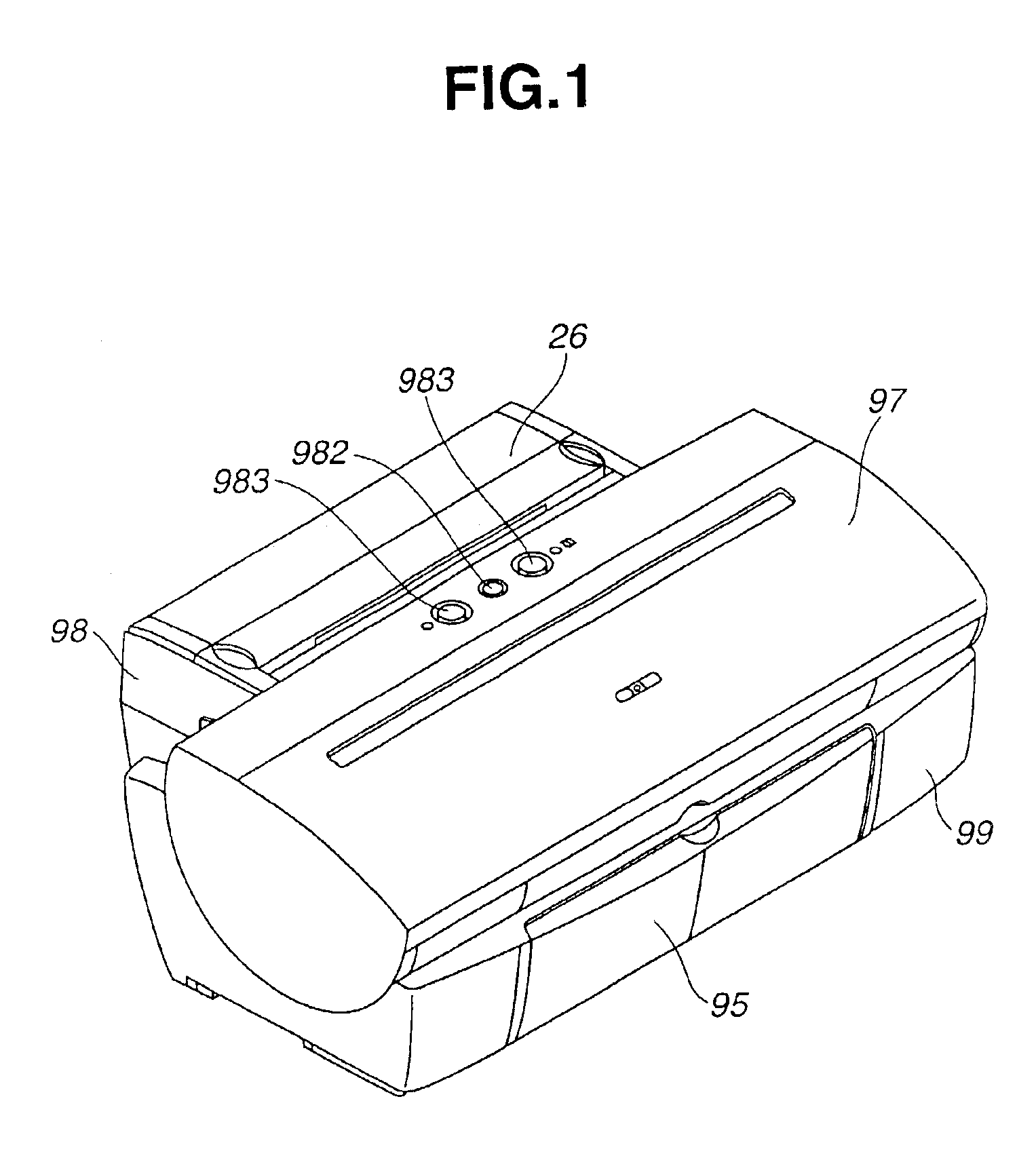
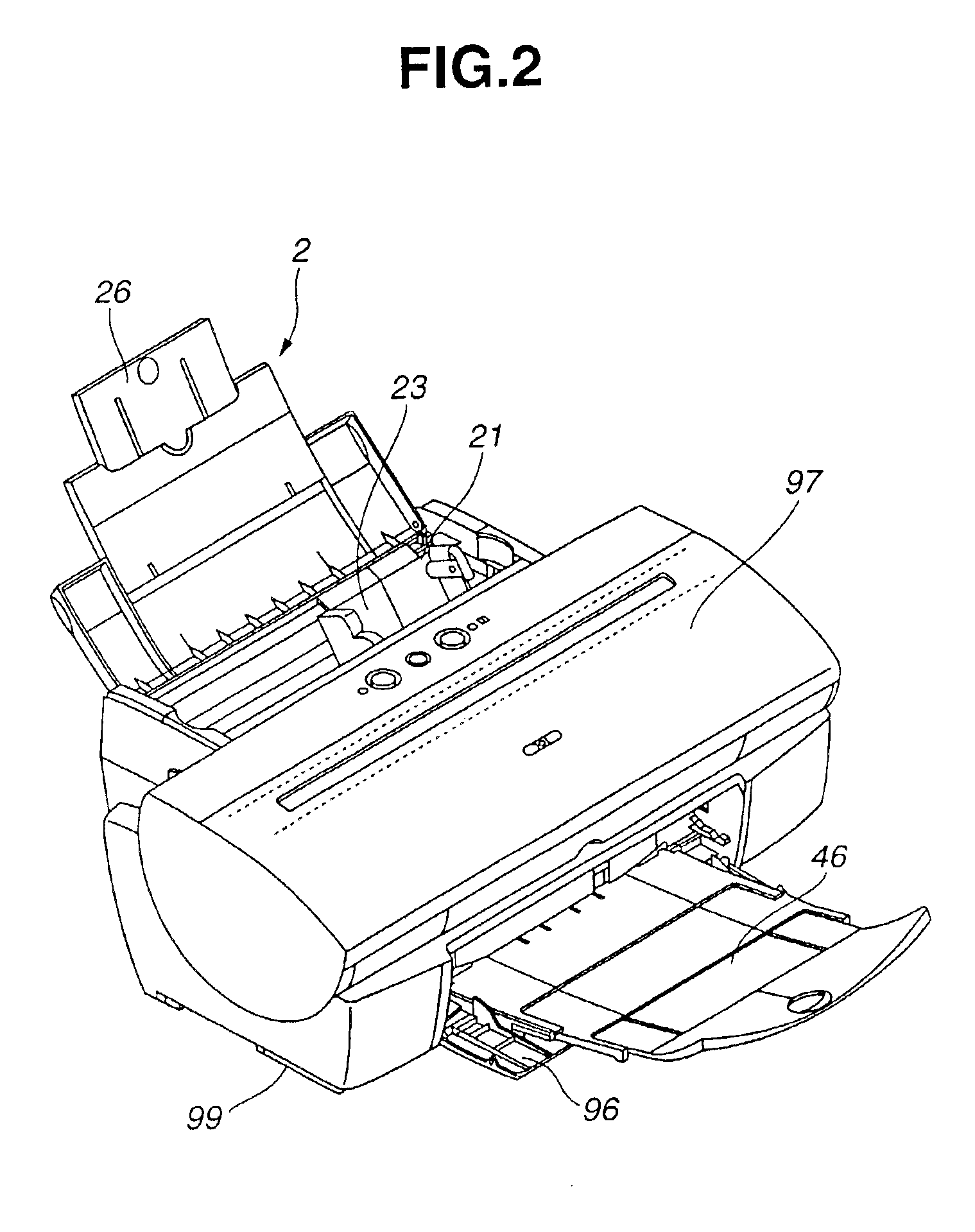
The basic configuration of a recording apparatus according to a first embodiment of the present invention will now be described with reference to FIGS. 1-5. FIGS. 1 and 2 are perspective views illustrating the recording apparatus of the first embodiment. FIGS. 3 and 4 are perspective views illustrating an internal mechanism of the recording apparatus of the first embodiment. FIG. 5 is a cross-sectional view of the recording apparatus of the first embodiment. The recording apparatus includes a sheet feeding unit 2, a sheet conveying unit 3, a sheet discharge unit 4, a carriage unit 5, a cleaning unit 6, a recording head 7, a unit 8 for conveying a special recording material (for example, a CD), and an electric unit. An outline of each of these units will now be sequentially described.

(A) Sheet Feeding Unit

As shown in FIG. 5, in the sheet feeding unit 2, a pressing plate 21 for mounting a standard sheet material, serving as an ordinary recording material, a sheet fee...

second embodiment

(Second Embodiment)

Next, a second embodiment of the present invention will be described in detail with reference to the drawings. The same components as those in the first embodiment are indicated by the same reference numerals, and further description thereof will be omitted. However, in each of the following embodiments, in order to facilitate understanding, some of these components will be again described while modifying the description.

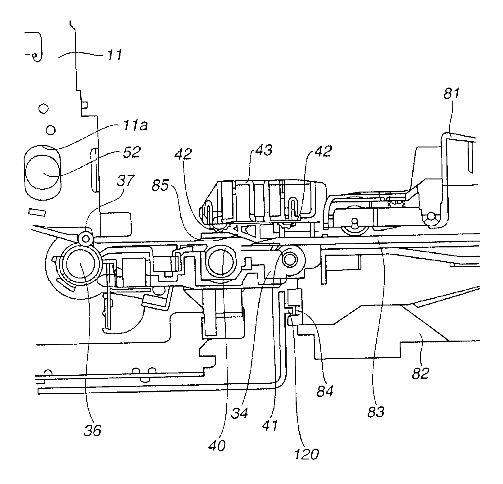
In the second embodiment, a slide cover 81 is slid by sliding a guide pin provided inside of a tray guide 82 along a guide groove 82 in the direction of an angle m (see FIG. 38). First, as shown in FIG. 39, the tray guide 82 is caused to enter the main body of the recording apparatus by sliding the tray guide 82 in the direction of an arrow Y. At that time, a hook 84 is swung in a clockwise direction by a guide rail 993. When the tray guide 82 is further slid, then, as shown in FIG. 40 indicating a principal portion, the hook 84 completely meshes ...

third embodiment

(Third Embodiment)

Next, a third embodiment of the present invention will be described in detail with reference to the drawings. The same components as those in the first and second embodiments are indicated by the same reference numerals, and further description thereof will be omitted.

In the third embodiment, a rotation knob 202 rotatable around a rotation shaft 202a is mounted at a tray guide 82. An arm 85 is slidable in the left and right directions of the tray guide 82, and is guided by upper and lower ribs with a space of about 1 mm above and below. A post 85a engages with a groove 202c of the rotation knob 202. By rotation of the rotation knob 202, the tray guide 82 is slid to the left and the right. When the rotation knob 202 is rotated in a clockwise direction from the state shown in FIG. 45, the arm 85 slides, to rotate a hook 84 in a counterclockwise direction by an engaging unit 85b. If the rotation knob 202 is rotated in a counterclockwise direction, the arm 85 protrudes...


PUM


Abstract

A recording apparatus can mount a special recording material, such as a compact disc (CD) or the like, in a state of being accommodated in a tray and perform recording on the special recording material. In this recording apparatus, by an operation of mounting a tray guide into the main body of the recording apparatus, an arm of the tray guide is inserted between a spur base for holding a spur, and a platen for holding sheet discharge rollers. The spur base thereby raises to separate the spur from the sheet discharge roller, and a space to allow passage of the tray is formed.

Description

BACKGROUND OF THE INVENTION1. Field of the InventionThe present invention relates to a recording apparatus, such as a printer or the like, and more particularly, to a recording apparatus in which recording can be performed on a recording material other than standard paper, and the recording material is mounted in the main body of the recording apparatus in a state of being accommodated in a tray-shaped unit.2. Description of the Related ArtConventionally, a recording apparatus, such as a printer or the like, is expected to perform recording on each type of recording material as well as standard paper. For example, recording is performed on cardboard, a card, a CD(compact disc)-R (recordable), or a DVD (digital versatile disc). Such a recording material is sometimes smaller or thicker than standard recording paper, and it is impossible to convey the recording material by conveying means for conveying standard paper. Even if it can be conveyed, problems may arise such as inferior conv...

Claims


Application Information

Patent Timeline
Patent Type & Authority Patents(United States)
IPC IPC(8): B41J13/00B41J13/10B41J3/407B41J2/01B41J29/13
CPCB41J13/103B41J3/4071
Inventor KAWAGUCHI, KOICHIROMURATA, SHINJIKANEKO, MASANORISUGIYAMA, NORIYUKISAITO, HIROYUKIIWAKURA, KOYA
Owner CANON KK
Why Eureka
Try Eureka