Dispenser and process

a technology of dispensing device and dispensing process, which is applied in the direction of pliable tubular container, transportation and packaging, internal fittings, etc., can solve the problem of extreme force load required to rupture the membrane, and achieve the effect of increasing or decreasing the amount of applied for

Inactive Publication Date: 2005-03-22
JAMES ALEXANDER CORP
View PDF57 Cites 30 Cited by
  • Summary
  • Abstract
  • Description
  • Claims
  • Application Information

AI Technical Summary

Benefits of technology

The present invention provides a dispenser for discharging either a liquid or solid material. To this end, there is a device provided having two adjacent chambers separated from each other by a novel rupturable web or fracturable membrane. The first chamber has a distal end and is a storage chamber for the material. The second chamber has a proximate end and receives the material when released from the first chamber by rupture of the membrane. The first and second chambers are defined by a peripheral wall with an elongated axis forming a sleeve or cylinder. After the material is added to the first chamber, the distal end, the end opposite from the membrane, is sealed to hold the material in the first chamber. The first chamber can be closed off or sealed by pressing the sides of the end of the chamber together and heat sealing or applying an adhesive. Alternatively, the first chamber can be sealed by applying a cap over the end of the tube. The membrane separating the chambers is provided with a weld seam and is broken by lateral force on the membrane to allow the fluid to flow from the first chamber into the second chamber. The thickness of the membrane can be varied, thereby either increasing or decreasing the amount of applied force needed to rupture the membrane.
In accordance with the invention, the web is preferably disk-shaped having a series of radial disposed uniform depressions on one surface of the disk and extending from a center point of the disk in the form, for example, of spokes on a wheel. The thickness of the disk is lesser at the depressions. When the disk is compressed by exerting pressure on the edge of the disk, the web breaks along the depressions forming a series of finger-like triangular projections extending from the face of the disk. Since the fingers are widest where they contact the container wall, the center section of the disk preferably opens first to material flow. The amount of material that can pass into the second chamber is controlled by the degree of opening which corresponds to the depressed areas and the pressure applied to the chamber. In a preferred embodiment, the depressed areas are formed on only one side of the disk but could also have depressed areas on both sides of the disk. The fingers formed as a result of the compression will extend in the direction of the flow of the material. This arrangement permits an even flow of the material.

Problems solved by technology

Conversely, extreme force loads are required to rupture the membrane by compressing the first chamber.

Method used


Image

  • Dispenser and process
  • Dispenser and process
  • Dispenser and process

Examples


Embodiment Construction

While this invention is susceptible of embodiment in many different forms, there is shown in the drawings and will herein be described in detail preferred embodiments of the invention with the understanding that the present disclosure is to be considered as an exemplification of the principles of the invention and is not intended to limit the broad aspect of the invention to the embodiments illustrated.

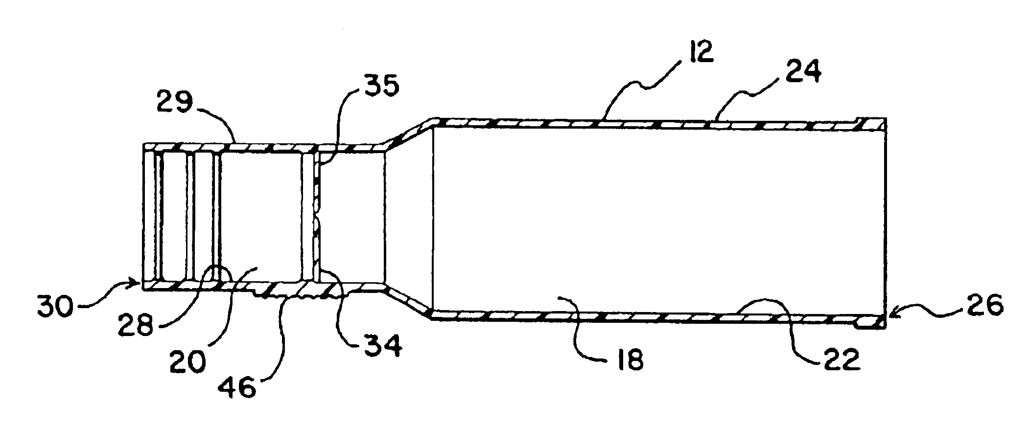
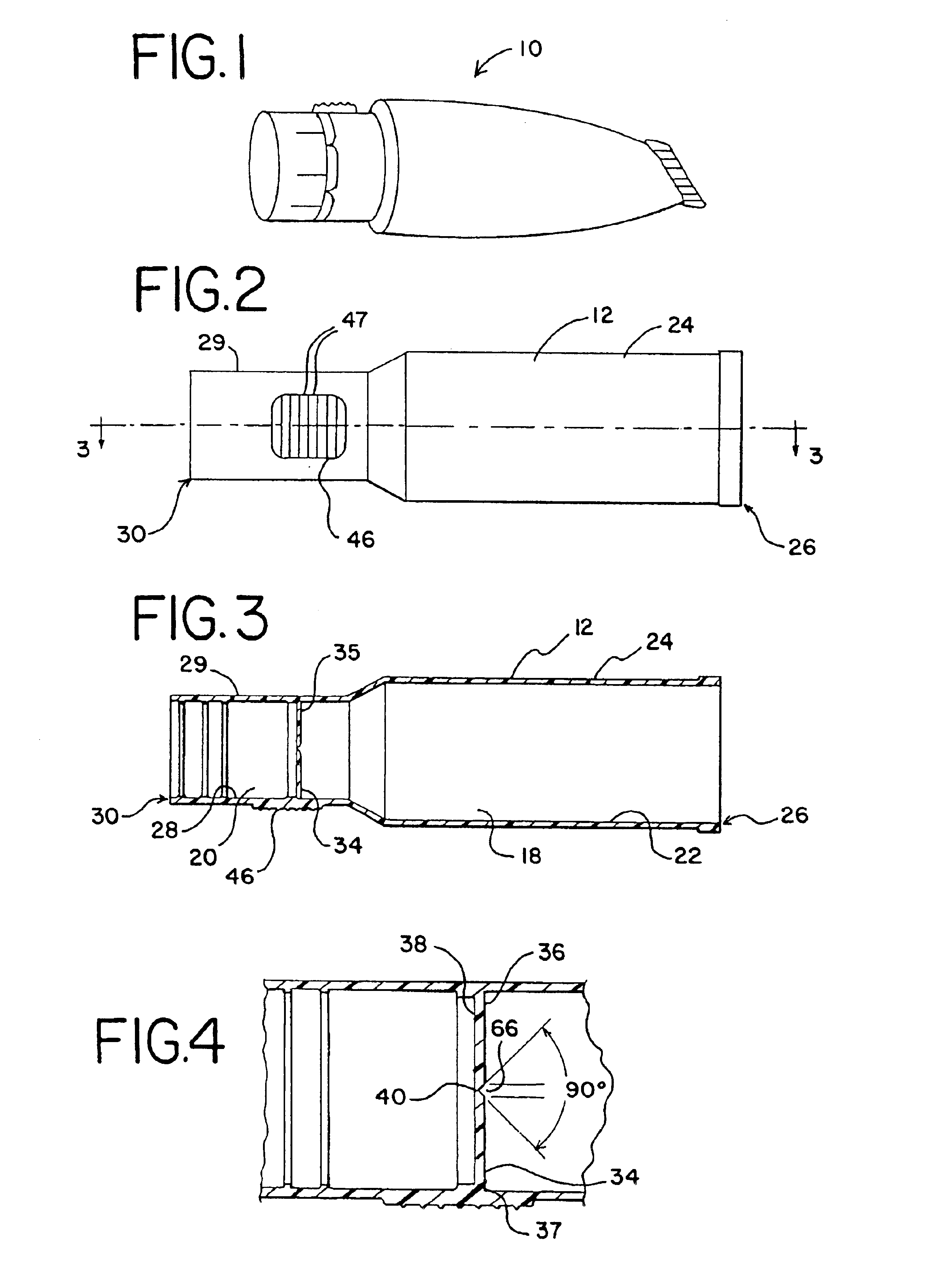
Referring to the drawings, FIG. 1 discloses a dispenser according to the present invention generally designated by the reference numeral 10. FIGS. 2 and 3 show the container 12 prior to having one end sealed as will be described in greater detail below. As shown in FIGS. 2 and 3, the dispenser 10 generally comprises a container 12 with an elongate axis L having a peripheral wall 16. In one preferred embodiment, the container 12 is cylindrical. However, the container 12 can be molded in numerous shapes, including an elliptical shape.

As further shown in FIGS. 2 and 3, the container 12 g...


PUM


Abstract

A dispenser (10) for use in dispensing liquid or solid material. The dispenser (10) includes wall portions forming a sealed first chamber (18) containing the material and wall portions forming a second chamber (20) and a molded, rupturable membrane (34) disposed between the first chamber (18) and the second chamber (20). The rupturable membrane (34) is preferably a circular disk with a series of molded radial depressions (40) or weld seams (40) extending from a center point of the disk. When pressure is applied directly to the membrane (34), the membrane (34) is fractured along the depressions (40) or weld seams (40). A method is provided for forming the dispenser (10) by injection molding.

Description

FEDERALLY SPONSORED RESEARCH OR DEVELOPMENTNot Applicable.TECHNICAL FIELDThe invention generally relates to a dispenser for a flowable substance and, in particular, the invention relates to a one piece fluid dispenser having two chambers separated by a membrane.BACKGROUND OF THE INVENTIONDifferent types of containers and dispensers for the distribution of material are known within the packaging industry. One example is described in U.S. Pat. No. 3,759,259 issued Sep. 18, 1973 to Andrew Truhan. The Truhan patent discloses a combination applicator and container for medicinal substances. The applicator includes a holder and a fibrous wadding of cotton. The container has flexible walls and a flat seal that spans the container opening. The flat seal is heat sealed to the interior surface of the container. The flat seal is perpendicular to the flexible walls and ruptures upon the application of inward force to the container side walls. In another embodiment, the flat seal includes one or ...

Claims


Application Information

Patent Timeline
Patent Type & Authority Patents(United States)
IPC IPC(8): B65D35/24B65D25/04B65D25/08
CPCB65D25/08B65D35/242Y10T428/15Y10T137/1692
Inventor MAY, RICHARD JAMES
Owner JAMES ALEXANDER CORP
Why Eureka
Try Eureka