Engine-generator arrangement

a technology of engine and gearbox, applied in the direction of shafts, couplings, dynamo-electric machines, etc., can solve the problems of destroying the generator, affecting the engine, structurally more complicated foundations or rigid frames for carrying torque forces,

Inactive Publication Date: 2005-03-22
JENBACHER
View PDF18 Cites 13 Cited by
  • Summary
  • Abstract
  • Description
  • Claims
  • Application Information

AI Technical Summary

Benefits of technology

The vibration decoupling effect between the internal combustion engine and the generator can however in principle be effected structurally in many different ways, preferably between elastomer elements, so that the vibrations from the engine are not passed to the generator. Design configurations as are already known per se in relation to elastic shaft couplings (pin couplings, dog couplings, bead or flange couplings, intermediate ring couplings, etc) are basically suitable.

Problems solved by technology

A disadvantage with this structure however is the transmission of vibration by way of the rigid intermediate members, which can adversely affect and ultimately ruin the generator 5.
A disadvantage with the structures shown in FIGS. 2 and 3 is the fact that such foundations or rigid frames for carrying the torque forces are structurally more complicated and expensive.

Method used


Image

  • Engine-generator arrangement
  • Engine-generator arrangement
  • Engine-generator arrangement

Examples


Embodiment Construction

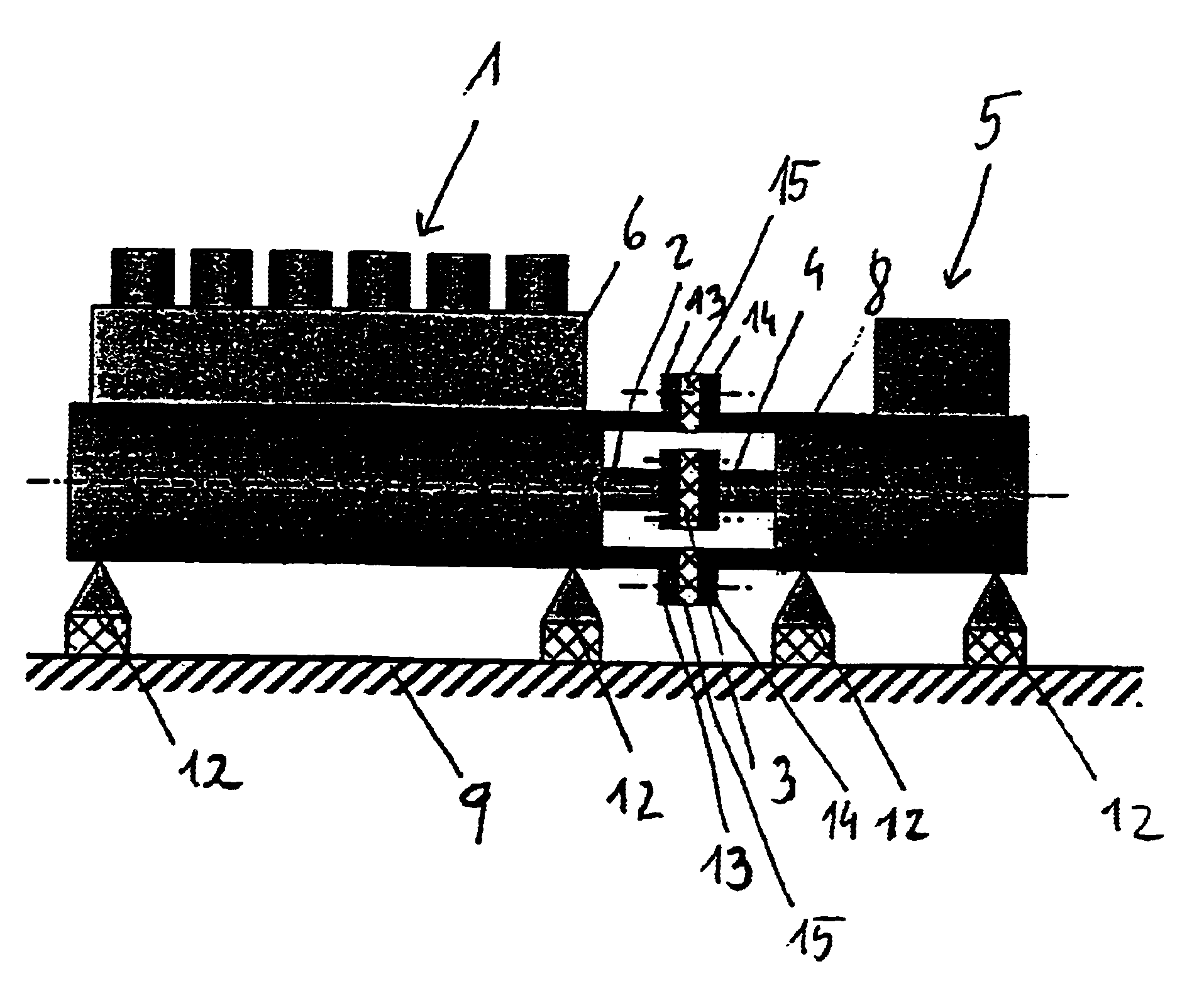
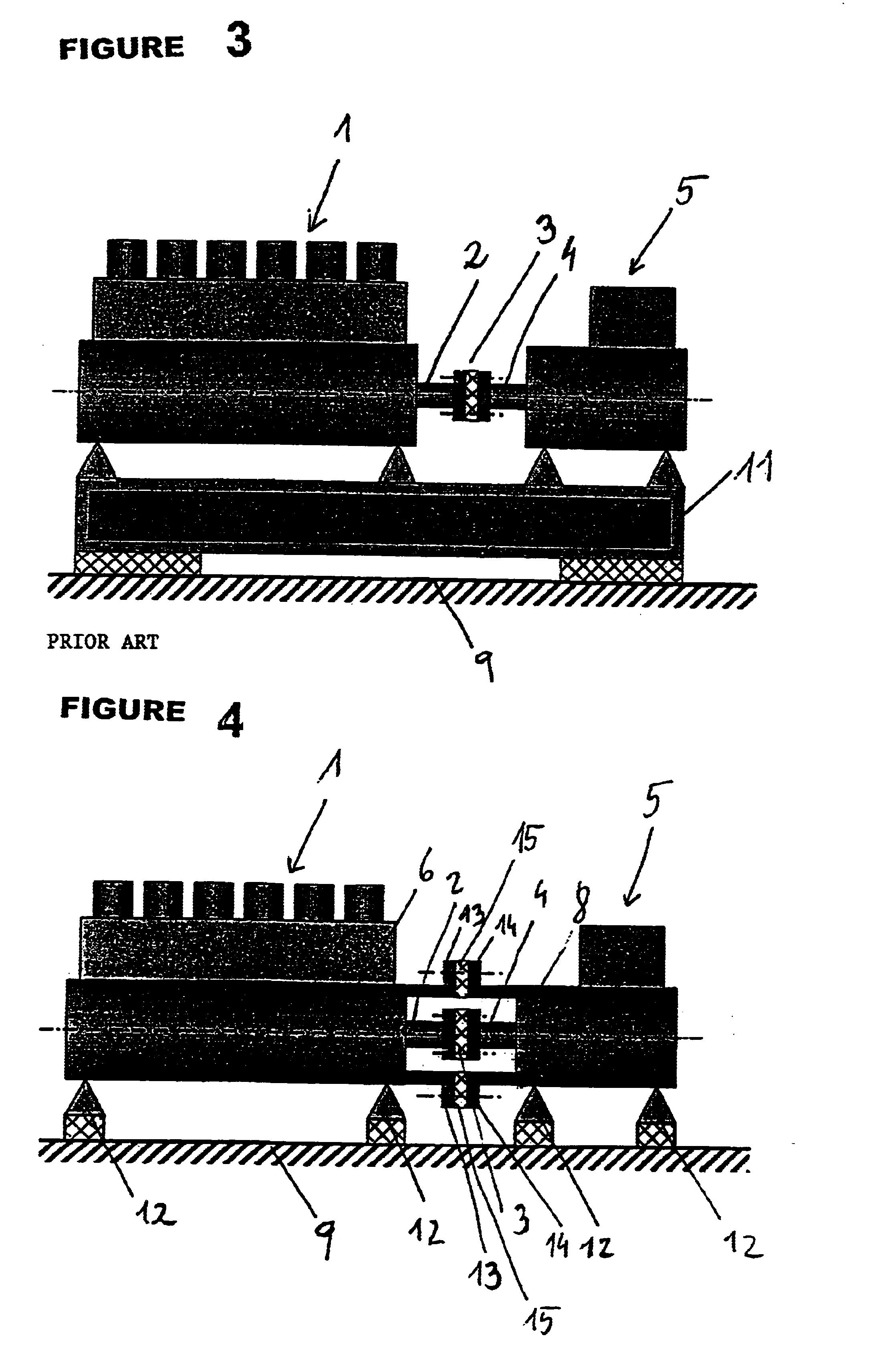
In the embodiment according to the invention as shown in FIG. 4, the internal combustion engine 1 drives by way of an output shaft 2 the drive shaft 4 of a generator 5. Both the internal combustion engine 1 and also the generator 5 are supported on the ground 9 by way of simple rubber-mounted supports 12. A rotationally and radially elastic coupling connects the output shaft 2 to the drive shaft 4.

Now, in accordance with the invention, it is provided that the engine casing 6 is connected elastically and preferably resiliently or rubber-elastically to the generator casing 8.

For that purpose, in the embodiment shown in FIG. 4, arranged on the engine casing 6 substantially around the output shaft 2 is a first annular flange 13. A second annular flange 14 is arranged around the generator casing 8, substantially around the drive shaft 4. Now, in accordance with the invention, the two annular flanges 13 and 14 are connected together rubber-elastically and with vibration decoupling, by way...


PUM


Abstract

An engine-generator arrangement comprising an internal combustion engine whose output shaft is connected to the drive shaft of the generator by way of an elastic coupling, wherein the engine casing of the internal combustion engine is connected elastically and preferably rubber-elastically to the generator casing of the generator.

Description

BACKGROUND OF THE INVENTION1. Field of the InventionThe invention concerns an engine-generator arrangement comprising an internal combustion engine whose output shaft is connected to the drive shaft of the generator by way of an elastic coupling.Engine-generator arrangements of that kind are used for example as modules for block heating and generating plants. The elastic coupling makes it possible to achieve rotational elasticity to compensate for shock torque loadings and damping of rotational oscillations as well as radial elasticity to compensate for shaft misalignments.2. Description of the Related ArtThe state of the art includes a structure as is shown in FIG. 1. The output shaft 2 of the internal combustion engine 1 is connected by way of an elastic coupling to the drive shaft 4 of the generator 5. The engine casing 6 of the internal combustion engine 1 is rigidly connected by way of connecting members 7 to the generator casing 8 of the generator 5. The entire engine-generato...

Claims


Application Information

Patent Timeline
Patent Type & Authority Patents(United States)
IPC IPC(8): F02B63/04F16F15/121F16F1/393F16F1/38F16F15/124F02B63/00F16F3/087F16F3/00H02K7/18H02K5/24F16D3/64
CPCF02B63/04H02K7/1815F16F3/0876F16F15/124H02K5/24F16F1/393F02B63/042F02B2063/045
Inventor HERDIN, GUNTHERMADERBOCK, MANFREDPLOHBERGER, DIETHARDMESSNER, ERICH
Owner JENBACHER
Why Eureka
Try Eureka