Filtering system for runoff water

a filtering system and runoff water technology, applied in water cleaning, filtration separation, separation processes, etc., can solve the problem of reservoir overflowing quickly, and achieve the effect of high flow ra

Inactive Publication Date: 2005-03-22
PANK THOMAS E
View PDF68 Cites 37 Cited by
  • Summary
  • Abstract
  • Description
  • Claims
  • Application Information

AI Technical Summary

Problems solved by technology

However, when the runoff water has a high rate of flow the reservoir soon overflows and the excess water flows directly to an outlet.

Method used


Image

  • Filtering system for runoff water
  • Filtering system for runoff water
  • Filtering system for runoff water

Examples


Embodiment Construction

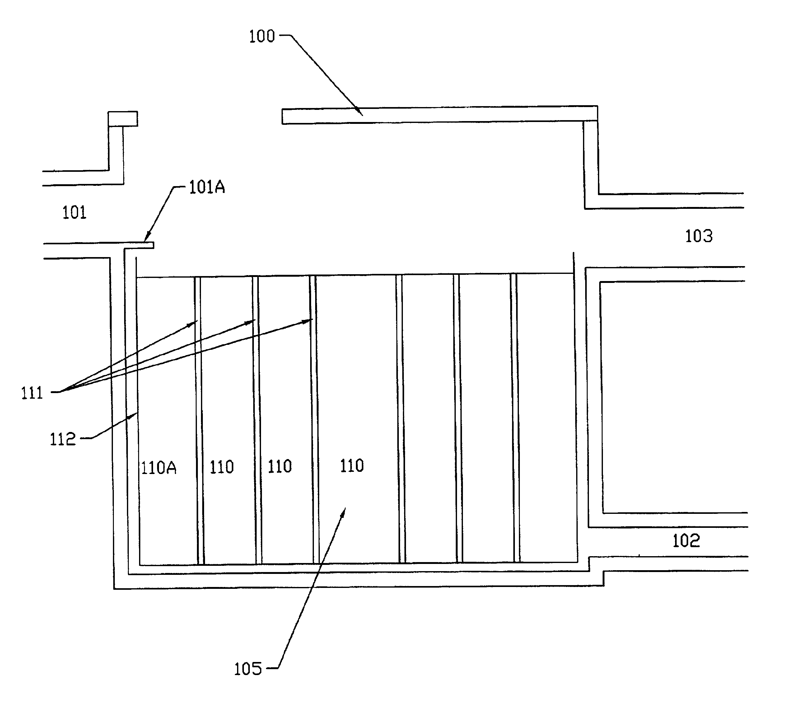
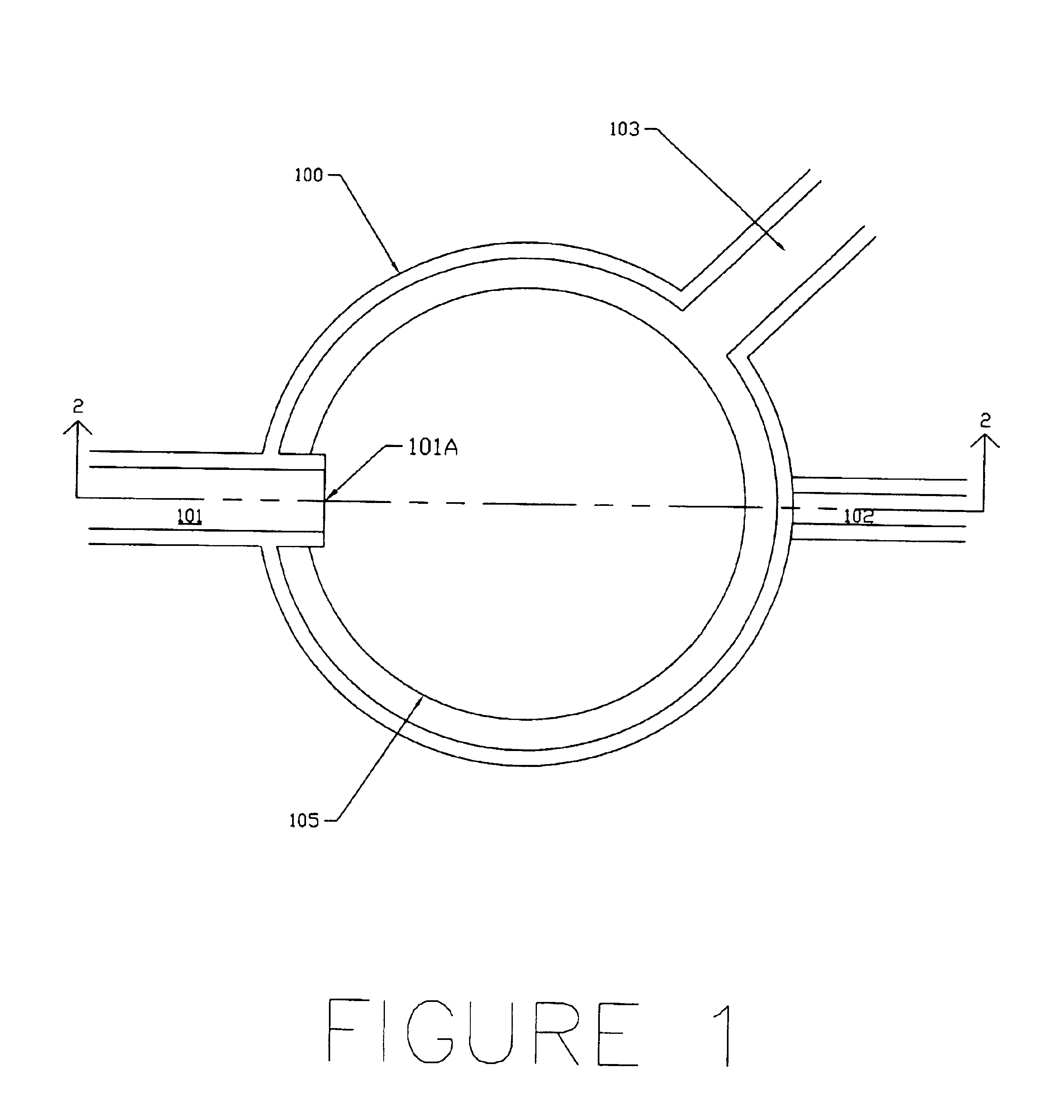
Parking lots and other paved areas build up contaminants such as oils during everyday use. During a storm, these oils are carried into the storm drain by the stormwater runoff, which is usually discharged to a river or stream. The present invention is a system for removing oils from stormwater runoff by using filtration.

The conventional prior art relies on gravity separation to remove oils from stormwater runoff. Free oils can be removed by this method, but emulsified and dissolved oils cannot. The present invention makes use of a fine filter media to trap those oils that cannot be removed in a conventional gravity separator. Used in conjunction with a gravity separator such as those described in U.S. Pat. Nos. 5,746,911 and 8,264,835, both to Pank, the present invention comprises a two stage process for the removal of oils from runoff water.

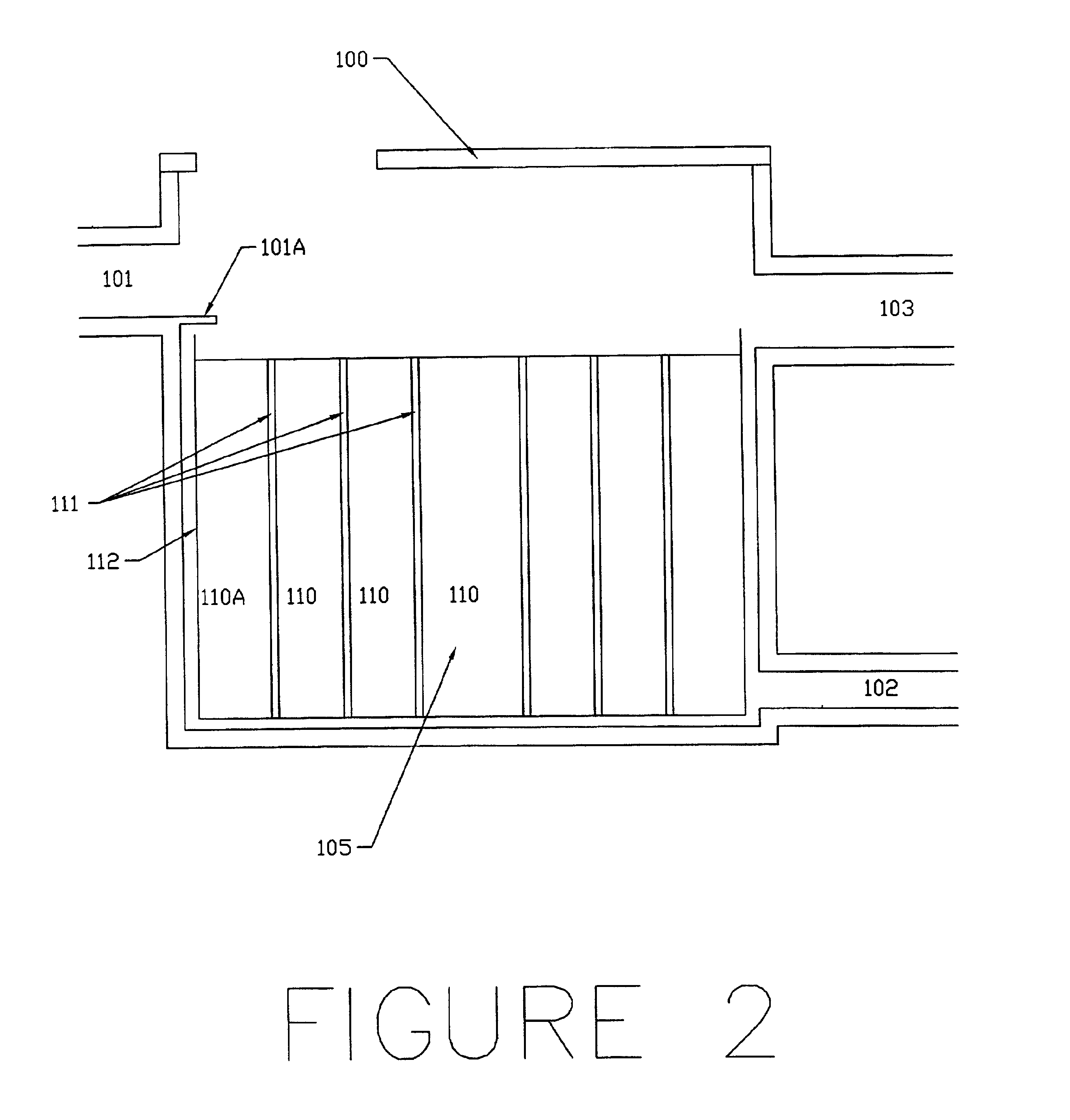
FIGS. 1 to 6 illustrate the preferred form of the invention.

The new filter has two opposing sides, one of which sides comprises the upper ends ...


PUM

PropertyMeasurementUnit
pressureaaaaaaaaaa
forceaaaaaaaaaa
gravityaaaaaaaaaa

Abstract

The present invention filters runoff water containing oil and an emulsion of oil and water. A tank receives the inlet water and feeds it to a reservoir which in turn feeds the water to the cylindrical filter cells. The water passing through the filter cells is received by a manifold which feeds the clean water to an outlet. However, when the runoff water has a high rate of flow the reservoir soon overflows and the excess water flows directly to an outlet. The reservoir may be either above or below the filter cells. If above, the water entering the inlet flows downward to a reservoir which is perforated to provide water to the filter cells. If, however, the reservoir is below the filter cells it has a perforated top which feeds the filter cells. The water in the reservoir is under pressure. The filter cells may be cylindrical. They have an inner vertical cylindrical passageway surrounded by one or more cylindrical layers. One filtering media is in said inner passageway. Each cylindrical layer provides a different filtering media. In one form of the invention the filtering media in the inner passageway is a coarse media and the filtering media in the other cylindrical layer or layers is a finer media. Each layer of the filter bounded by a porous barrier. Surrounding, and spaced from, the outermost barrier is an outer wall. The space between the outermost barrier and the wall forms a drain for feeding the filtered liquid to an output.

Description

BACKGROUND OF THE INVENTIONParking lots, the roads of filling stations and other places have oil and / or an emulsion of oil and water in the runoff water. These oils have been removed from the runoff water by a two stage process. Such a process includes first gravity separation which removes all oil other than the emulsion of oil and water from the runoff water, and secondly a filter for removing emulsion.The present invention is an improved filtering system for use as the second of the above two stages.Cylindrical filters, having two or more concentric layers, through which the liquid to be filtered pass in a radial direction are old, see U.S. Pat. No. 2,742,160 to Fogwell, U.S. Pat. No. 3,442,391 to Bozek, and U.S. Pat. No. 5,811,002 to Felber. Moreover, patents disclosing filters for drainage water include U.S. Pat. No. 6,027,639 to Lenhart, Jr. and U.S. Pat. No. 6,190,545 to Williamson.SUMMARY OF THE INVENTIONThe runoff water which is processed by the present invention may vary f...

Claims


Application Information

Patent Timeline
Patent Type & Authority Patents(United States)
IPC IPC(8): B01D24/00B01D17/02C02F1/28E03F5/14E03F5/16C02F1/40
CPCB01D17/0208B01D24/005C02F1/28E03F5/16B01D17/045B01D17/08B01D17/10B01D24/008B01D24/042B01D24/08B01D24/263B01D24/22C02F1/40C02F2103/001
Inventor PANK, THOMAS E.
Owner PANK THOMAS E
Why Eureka
Try Eureka