Microarray chip and method for indexing the same

a microarray and chip technology, applied in the field of microarray chips, can solve the problems of manual input input error, cost of devices such as letter or barcode readers,

Inactive Publication Date: 2005-03-22
HITACHI SOFTWARE ENG
View PDF13 Cites 17 Cited by
  • Summary
  • Abstract
  • Description
  • Claims
  • Application Information

AI Technical Summary

Problems solved by technology

As a result, cost of devices such as a letter or barcode reader, input error in case of manual input and the like have been the problems.

Method used


Image

  • Microarray chip and method for indexing the same
  • Microarray chip and method for indexing the same
  • Microarray chip and method for indexing the same

Examples


Embodiment Construction

Hereinafter, embodiments for carrying out the present invention will be described with reference to the drawings.

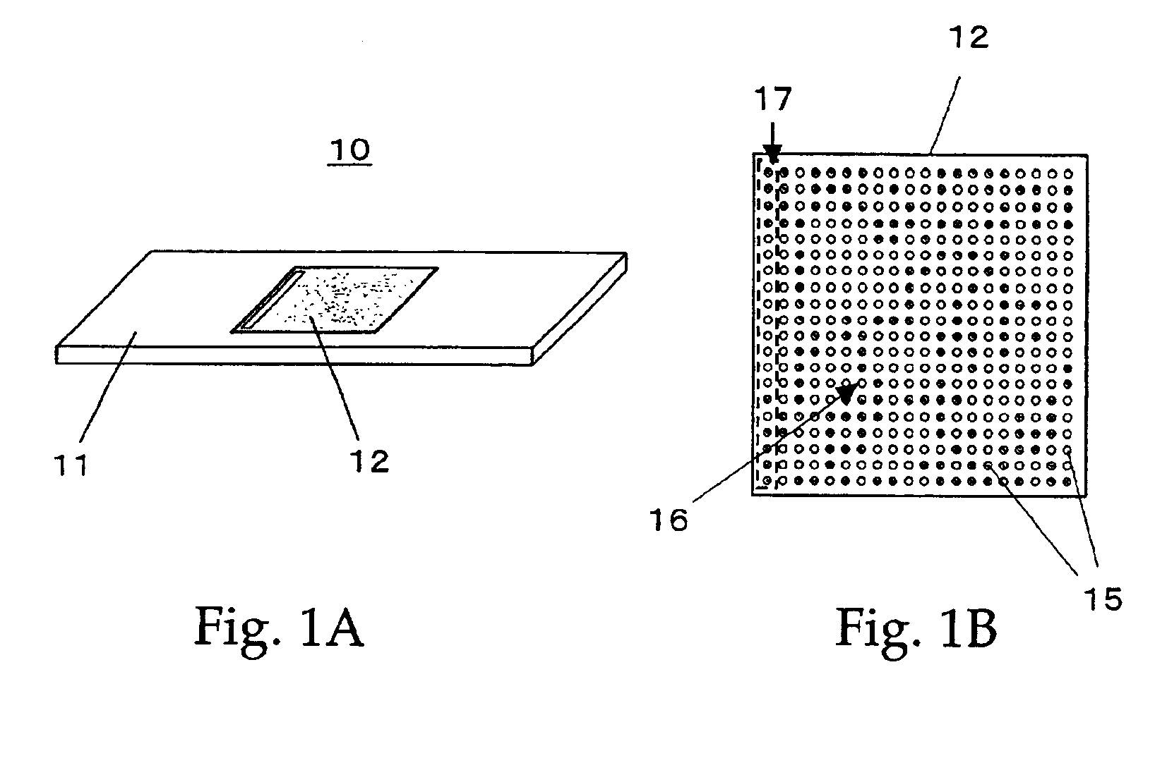
FIGS. 1A and 1B are schematic views showing an exemplary microarray chip provided with a microarray index of the invention. As shown in FIG. 1A, the microarray chip 10 includes a support (chip) 11 such as a glass slide, or a nylon or nitrocellulose membrane, and a element region 12 provided on the support 11. As shown in FIG. 1B, the element region 12 is provided with a microarray 16 in which element spots 15 are high-densely arranged in a two-dimensional array formation by depositing biopolymers such as DNAs or proteins prepared in wells (not shown) on the chip 11 using a spotter (arrayer). Some of the element spots 15 arranged in a two-dimensional array formation to construct the microarray 16 are used as a microarray index 17 as will be described below.

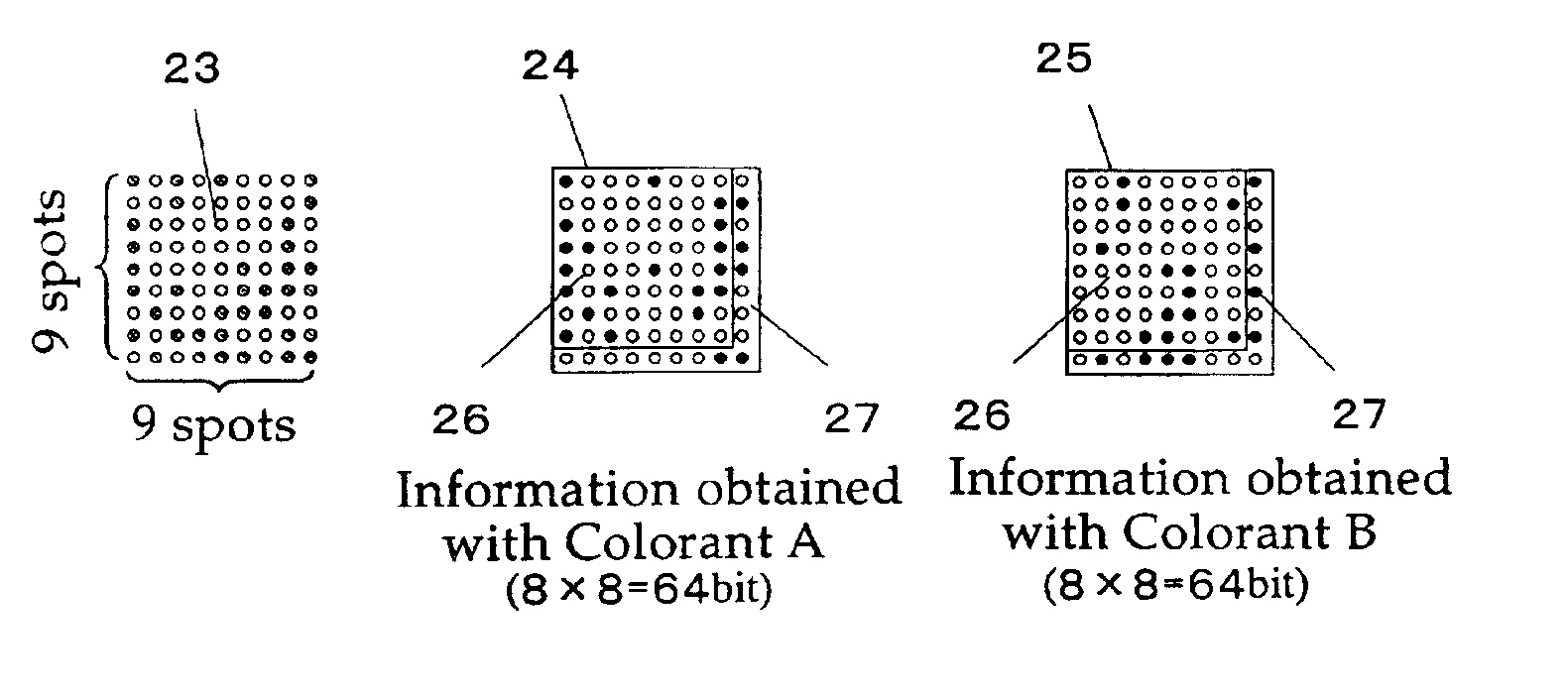
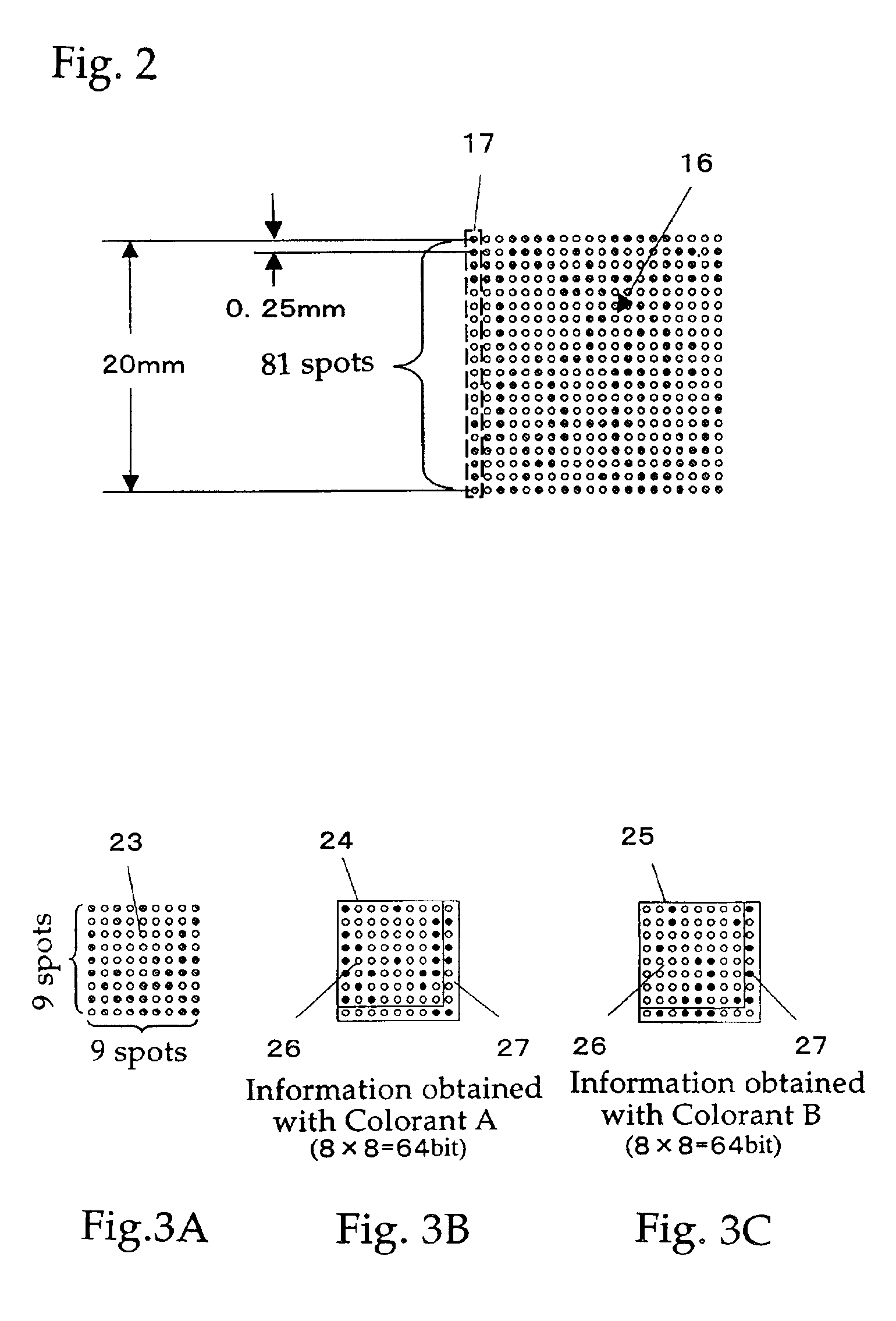
FIG. 2 is a view showing an example of the microarray 16 provided with a microarray index 17 which has an information ...


PUM

PropertyMeasurementUnit
rotation anglesaaaaaaaaaa

Abstract

A method for indexing and coding element information of at least one biological element provided on a microarray chip thereby identifying the microarray chip. Some of the element spots arranged on the microarray chip are used as index spots to be selectively provided with at a detective colorant. By doing so, the microarray chip is specified, and the element information as well as experimental information of the chip is automatically managed.

Description

TECHNICAL FIELDThe present invention relates to a microarray chip having a plurality of biopolymer spots arranged thereon such as DNAS or the like that specifically hybridize with particular DNAs or proteins, and to a method for indexing the microarray chip for identification.BACKGROUND ARTIn the field of molecular biology, microarray chips, as represented by a biochip on which biopolymers such as DNAs or proteins are high-densely immobilized, have lately and rapidly become of interest. For an experiment using the microarray chip, numbers of supports (chips) with diverse types of elements (probes) immobilized thereon are produced. The elements on each chip are subjected to reaction with a sample (target) of a test subject. The difference of the reaction between the elements and the sample on one chip may be detected by a single experiment. The difference of the reaction between the same element collections on a plurality of chips may be detected by repeating experiments under differ...

Claims


Application Information

Patent Timeline
Patent Type & Authority Patents(United States)
IPC IPC(8): B01J19/00C12Q1/68C12M1/00C40B40/06C12N15/09C40B40/10G01N33/53G01N33/566G01N37/00
CPCB01J19/0046C12Q1/6837C40B40/10B01J2219/00529B01J2219/00536B01J2219/00542B01J2219/00545B01J2219/00547B01J2219/00572B01J2219/00576B01J2219/00596B01J2219/00608B01J2219/0061B01J2219/00612B01J2219/00621B01J2219/00659B01J2219/00707B01J2219/00722B01J2219/00725C40B40/06B01J2219/00527
Inventor TAMURA, TAKUROYAMAMOTO, KENJIWATANABE, TOSHIMASAYOSHII, JYUNJI
Owner HITACHI SOFTWARE ENG
Why Eureka
Try Eureka