System and method for non-contact measurement of 3D geometry

a non-contact, three-dimensional technology, applied in the direction of measuring devices, instruments, using optical means, etc., can solve the problems of indeterminate or inaccurate measurements in dimly lit scenes, so as to prevent minimize the risk of mistaken or undetermined, and achieve the effect of preventing the measurement of surface edges

Inactive Publication Date: 2015-04-16
GALIL SOFT
View PDF9 Cites 34 Cited by
  • Summary
  • Abstract
  • Description
  • Claims
  • Application Information

AI Technical Summary

Benefits of technology

[0083]One possible advantage of the current system and method is that they enable the 3D reconstruction of at least a portion of a scene at a single time-slice (i.e. one video frame of the imaging sensors), which makes it advantageously effective when scenes are dynamic (i.e. containing for example moving objects or people).
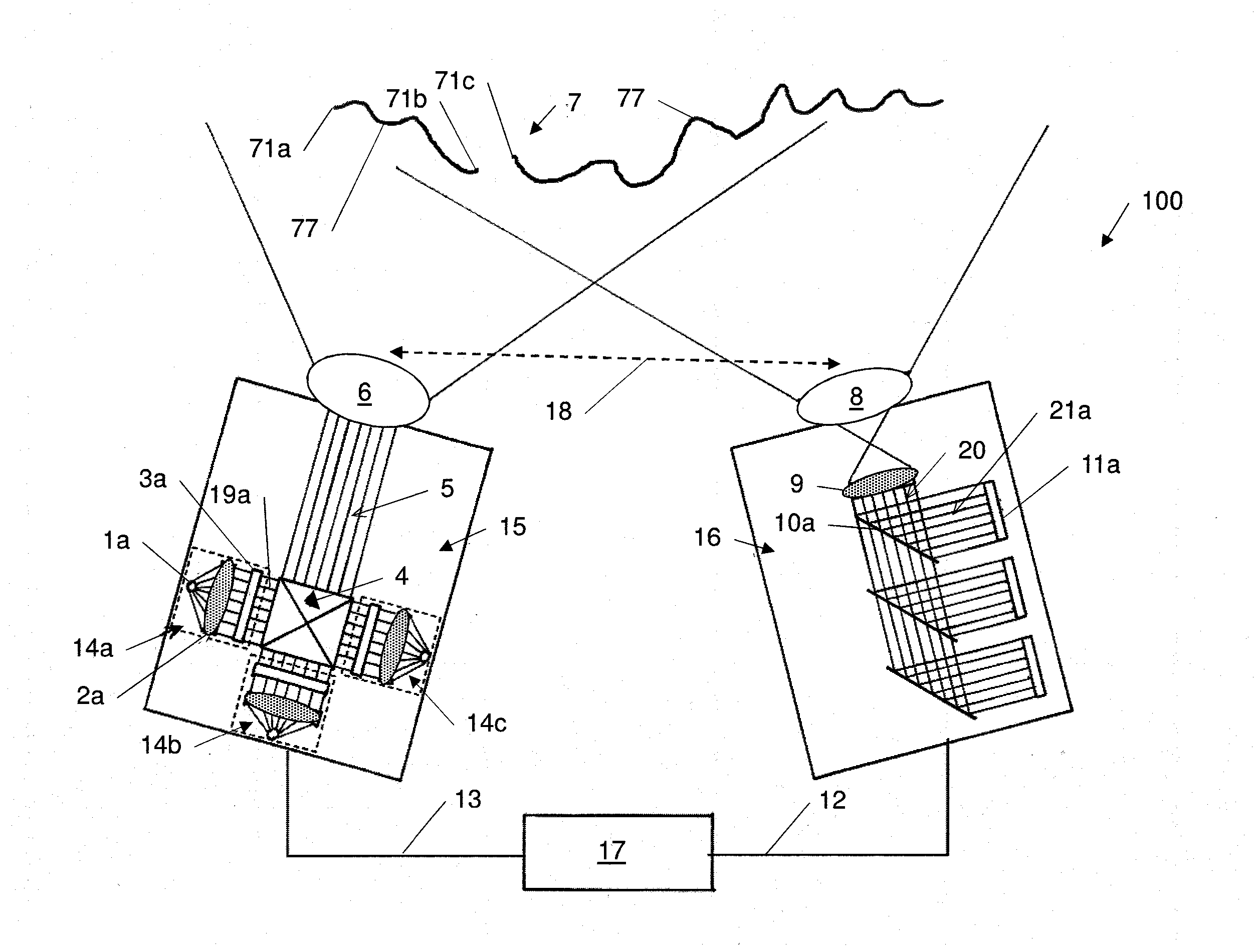
[0084]Another possible advantage of the present system and method is that they require a minimal area in the pattern (i.e. a single cell). Therefore, the smallest surface region on the surface 77 of scene 7 that can be measured by using the present coding method may be smaller than those achieved by using coding methods of prior art. Using the present coding method therefore allows for measurements up to the very edges 71x of the surface 77, while minimizing the risk of mistaken or undetermined code-word decoding.
[0085]Furthermore, larger coding-windows may be partially projected onto separate surfaces, separating a cell from its coding neighborhood, and therefore, may prevent the measurements of surface edges. Using the present coding method therefore possibly allows for measurements up to the very edges of surfaces while potentially minimizing the risk of mistaken or undetermined code-word decodi...

Problems solved by technology

Reconstruction techniques based on this approach, however, may yield indeterminate or inaccurate measurements when applied to dynamic scenes, where objects, animals, or humans may move before the projection sequence has been completed.
However, this approach may not lead to a denser measurement (i.e. smaller shapes, or smaller spacing) and may lead to indeterminate or incorrect measurements in dimly lit scenes and for color-varying surfaces.
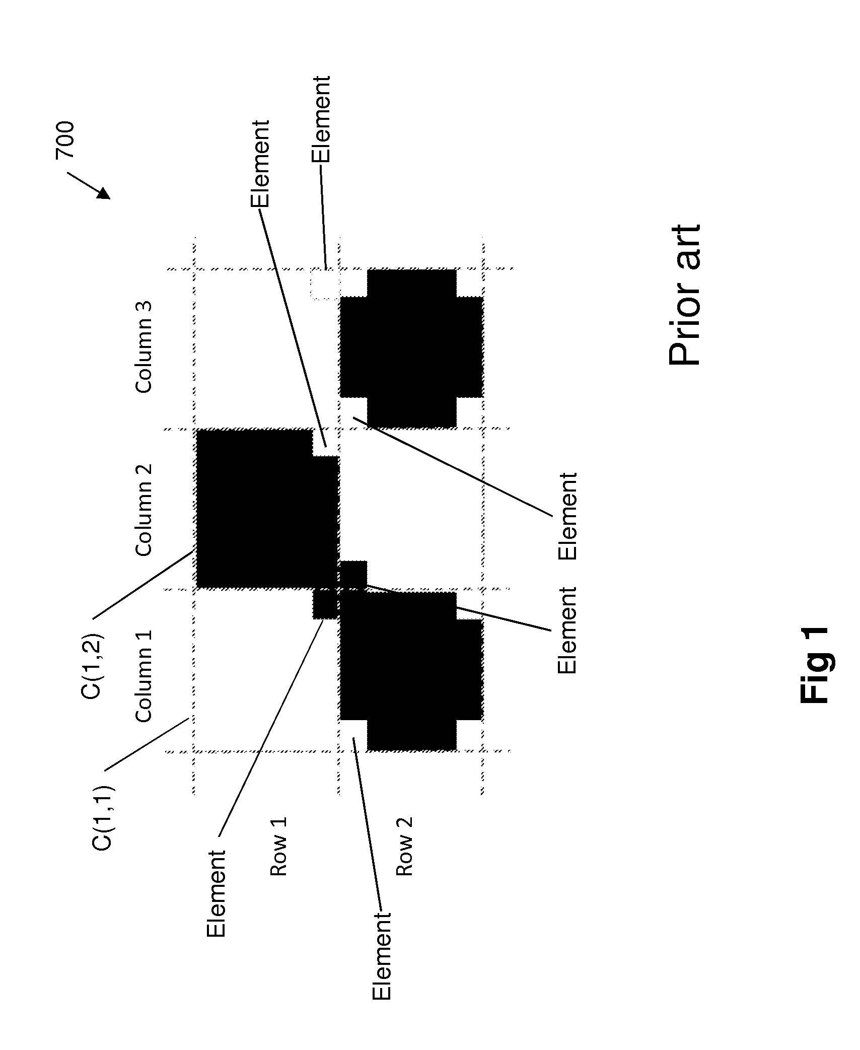
The relatively small number of code-words yielded by spatial-coding methods may span but a small portion of the imaged scene,...

Method used


Image

  • System and method for non-contact measurement of 3D geometry
  • System and method for non-contact measurement of 3D geometry
  • System and method for non-contact measurement of 3D geometry

Examples


Embodiment Construction

[0102]Before explaining at least one embodiment of the invention in detail, it is to be understood that the invention is not necessarily limited in its application to the details set forth in the following description or exemplified by the examples. The invention is capable of other embodiments or of being practiced or carried out in various ways.

[0103]The terms “comprises”, “comprising”, “includes”, “including”, and “having” together with their conjugates mean “including but not limited to”.

[0104]The term “consisting of has the same meaning as “including and limited to”.

[0105]The term “consisting essentially of means that the composition, method or structure may include additional ingredients, steps and / or parts, but only if the additional ingredients, steps and / or parts do not materially alter the basic and novel characteristics of the claimed composition, method or structure.

[0106]As used herein, the singular form “a”, “an” and “the” include plural references unless the context c...


PUM


Abstract

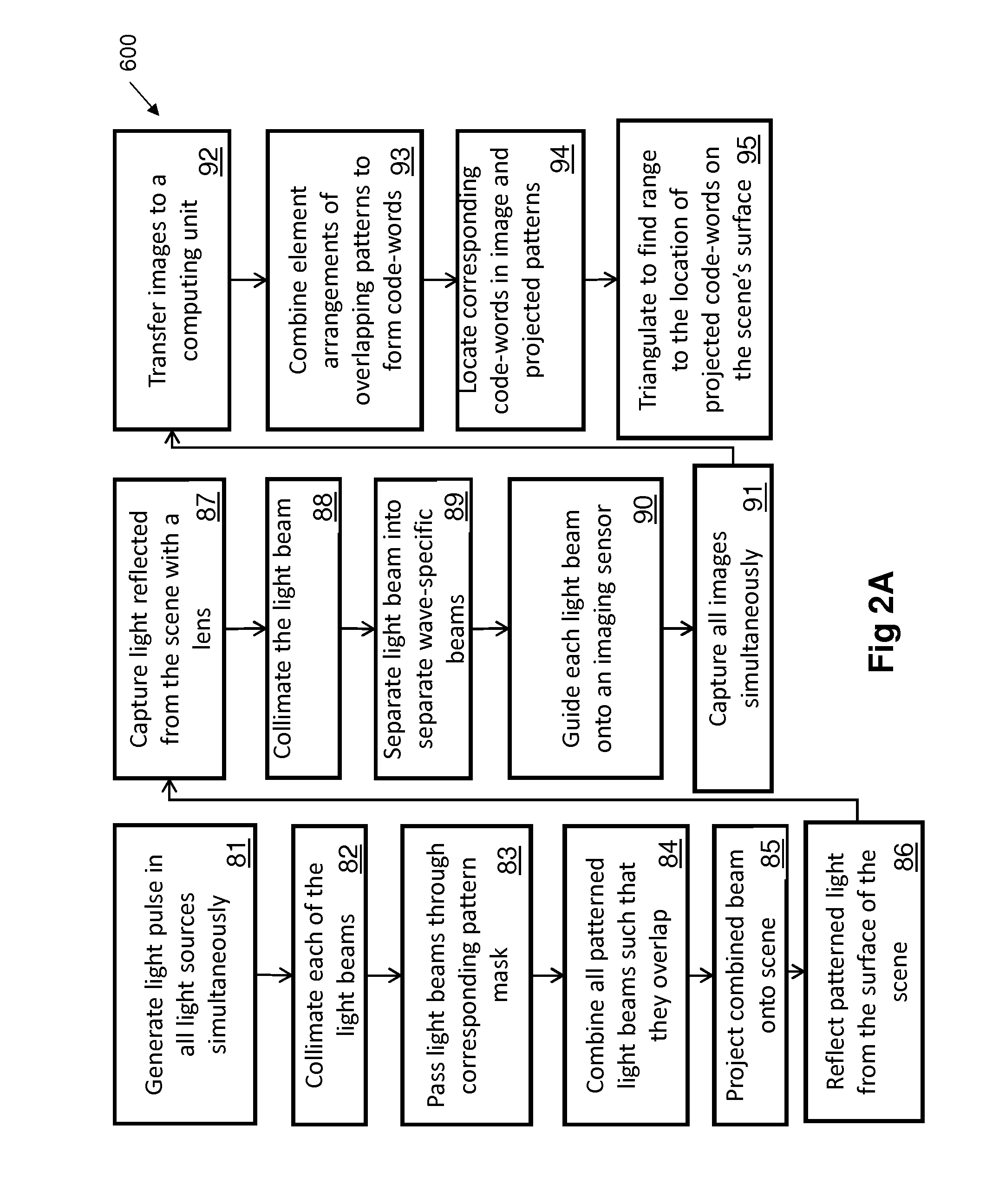
A method for the non-contact measurement of a scene's 3D geometry is based on the concurrent projection of multiple and overlapping light patterns of different wavelengths and/or polarity onto its surfaces. Each location in the overlapping light patterns is encoded (code-word) by the combined arrangements of code elements (code-letters) from one or more of the overlapping patterns. The coded light reflected from the scene is imaged separately for each wavelength and/or polarity by an acquisition unit and code-letters are combined at each pattern location to yield a distinct code-word by a computing unit. Code-words are then identified in the image, stereo-matched, and triangulated, to calculate the range to the projected locations on the scene's surface.

Description

FIELD OF THE INVENTION[0001]The subject matter of the current application relates to a system and measurement methods for reconstructing three-dimensional objects based on the projection and detection of coded structured light patterns.BACKGROUND OF THE INVENTION[0002]This invention pertains to the non-contact measurement of three-dimensional (3D) objects. More particularly, the invention relates to measurement methods based on the projection and detection of patterned light to reconstruct (i.e. determine) the 3D shape, size, orientation, or range, of material objects, and / or humans (hereinafter referred to as “scenes”). Such methods, known as “active triangulation by coded structured light” (hereinafter referred to as “structured light”), employ one or more light projectors to project onto the surfaces of the scene one or more light patterns consisting of geometric shapes such as stripes, squares, or dots. The projected light pattern is naturally deformed by the 3D geometry of surf...

Claims


Application Information

Patent Timeline
IPC IPC(8): G01B11/25
CPCG01B11/25G01B11/2509G01B11/2513
Inventor FLASCHER, ITTAI
Owner GALIL SOFT
Why Eureka
Try Eureka