Method for transforming bandpass filters to facilitate their production and resulting devices

a bandpass filter and production method technology, applied in the field of circuit transformation, can solve the problems of filter cost and often their insertion loss

Inactive Publication Date: 2005-03-22
FRANCE TELECOM SA
View PDF6 Cites 15 Cited by
  • Summary
  • Abstract
  • Description
  • Claims
  • Application Information

AI Technical Summary

Benefits of technology

By transformation using known narrow band equivalences (for example see references [7] and [23 to 26]), it is possible to replace transformers remaining at the ends of the filter by two impedances with opposite signs (C and L or C and −C′ or L and −L′) forming a Gamma (Γ) or a Tau (τ) depending on the transformation ratio. Steps are frequently taken such that one of the components located at the corresponding end (or a capacitance resulting from the decomposition of the original capacitances into three parts, or an original inductance for which the value was modified by displacement of transformers) is absorbed in this transformation or is replaced by another component with the same nature and with a different value. The result is that the number of components is not significantly increased (which is a means of absorbing negative values that can occur for example in the separation of capacitances).
Much of the advantage of the process proposed within the framework of this invention is the potential use of these additional degrees of freedom to make it more economic to make LC filters, or to enable the use of distributed dipoles that can be manufactured economically and / or which have more attractive characteristics within a given frequency range, under favourable conditions.

Problems solved by technology

The cost of filters, and often their insertion losses, depends largely on the number of inductances (and / or resonators) used since inductances and the various resonator types are significantly more expensive than capacitors.

Method used


Image

  • Method for transforming bandpass filters to facilitate their production and resulting devices
  • Method for transforming bandpass filters to facilitate their production and resulting devices
  • Method for transforming bandpass filters to facilitate their production and resulting devices

Examples


Embodiment Construction

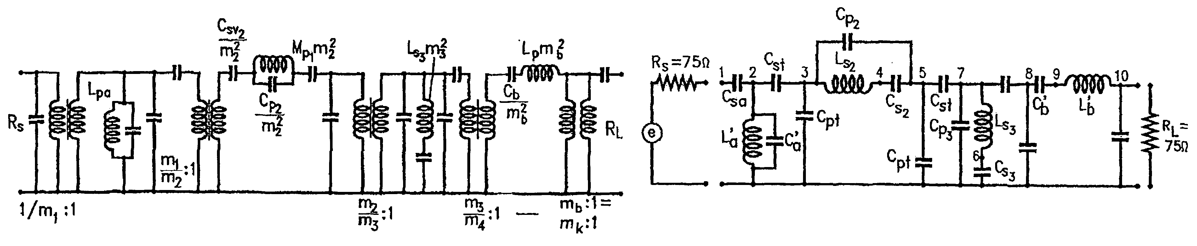
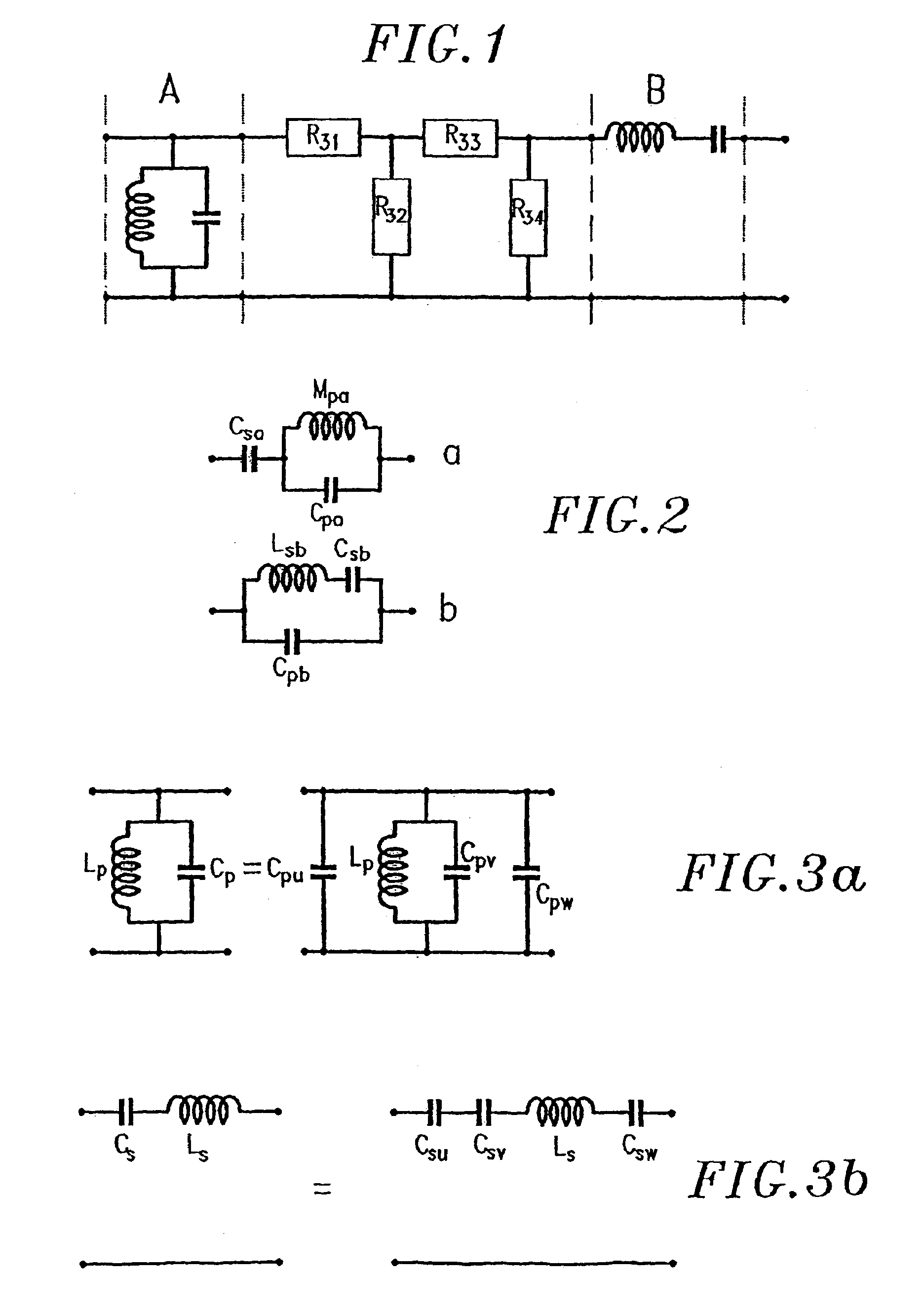
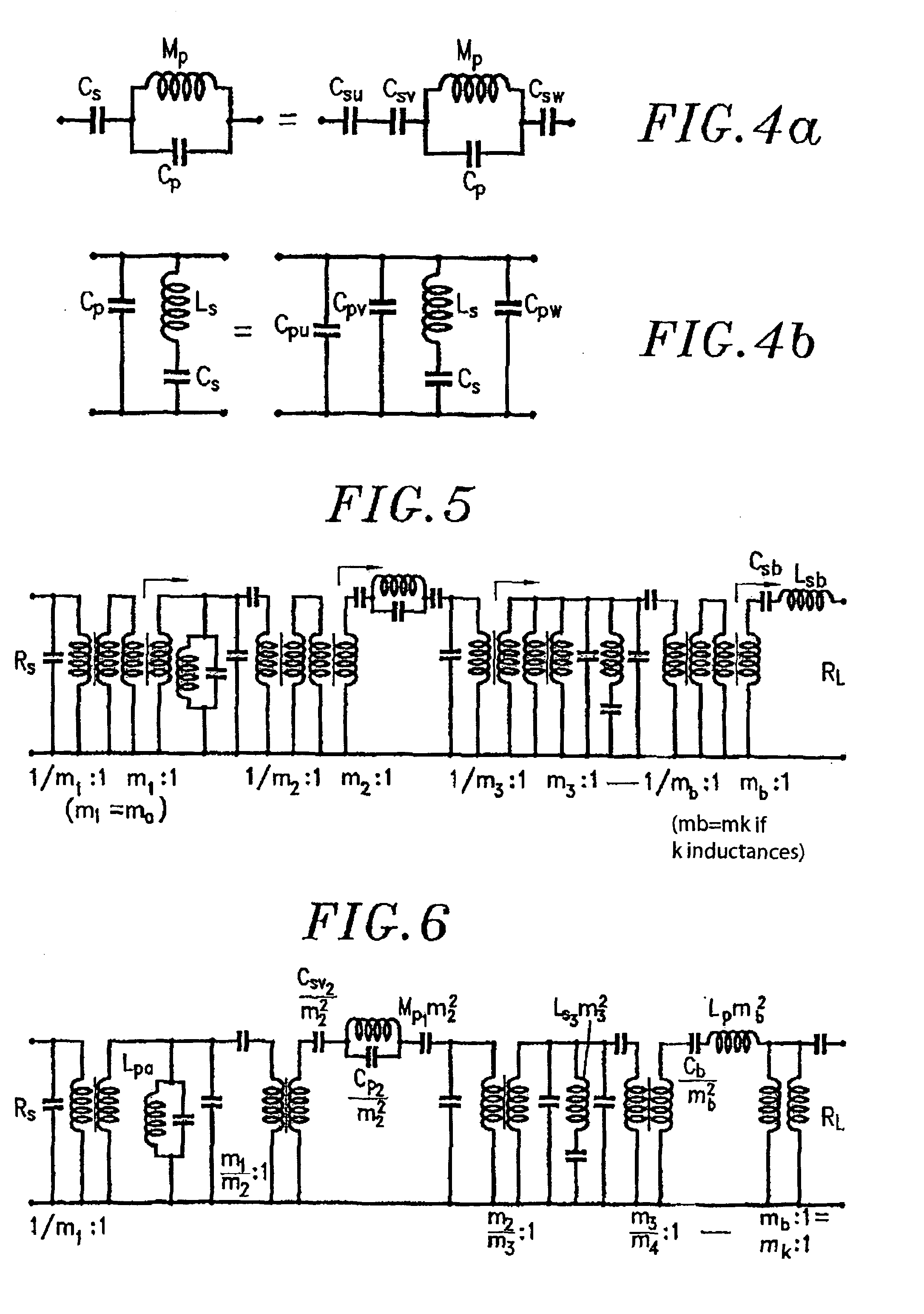
The systematic and global process for transformation of “minimum inductance” pass band filters and several other filter topologies according to the present invention, is intended to obtain filters using only one (or few) determined value(s) of inductances, or using dielectric resonators with the same characteristic impedance, or using piezoelectric resonators with approximately or exactly the same capacitance ratios and approximately or exactly the same inductances. This process also has advantages other than those mentioned above, such as the choice of equal values for some capacitances or the choice of typical off-the-shelf values for some capacitances. The process is equally applicable under similar conditions to connection filters composed of filters made according to previously mentioned technologies.

The process will be described principally for the case of filters with a minimum number of inductances that are among the most general filters, and in practice among the most usefu...


PUM


Abstract

The invention concerns a method for optimizing elements of a narrow or intermediate band bandpass filter whereof the LC prototype has been determined. The invention is characterized in that it comprises steps which consist in: (i) breaking down several parallel or series capacitors of resonators with X elements, (ii) inserting pairs of transformers between the first and second separated element and the rest of the resonator, (iii) displacing the residual transformers to modify the impedance levels of the resonators, and (iv) absorbing the residual transformers by transformation. The invention also concerns the resulting filters.

Description

The present invention relates to the field of pass band filters.INVENTION GENERAL PURPOSEThe present invention relates to a process for transformation of a circuit for the manufacture of high performance filters or multiplexers under acceptable technical and economic conditions.It is used to make pass band filters and multiplexers from prototypes with different topologies with response types varying from the simplest to the most general, and only using inductances all equal to fixed values (or only a small number of different predetermined values) to maximize performances and / or minimize the cost and / or predetermined values of capacitances.It is also used to make filters exclusively using dielectric resonators with the same characteristic impedance, or piezoelectric resonators with approximately or exactly the same ratio of capacitances and with similar or equal inductances.The process can be applied to hybrid filters or multiplexers using inductances and dielectric resonators and / o...

Claims


Application Information

Patent Timeline
Patent Type & Authority Patents(United States)
IPC IPC(8): H03H7/01
CPCH03H7/0115H03H2260/00
Inventor VEYRES, CAMILLEDETAINT, JACQUES
Owner FRANCE TELECOM SA
Why Eureka
Try Eureka