
Glove mouse with virtual tracking ball

a mouse and tracking ball technology, applied in the field of mouse, can solve the problems of lack of dexterity, unstable position control of the cursor, easy to operate, etc., and achieve the effect of efficient and precise control of the movement of the cursor

Inactive Publication Date: 2005-03-22
NATIONAL CHUNG HSING UNIVERSITY
View PDF7 Cites 56 Cited by
  • Summary
  • Abstract
  • Description
  • Claims
  • Application Information

AI Technical Summary

Benefits of technology

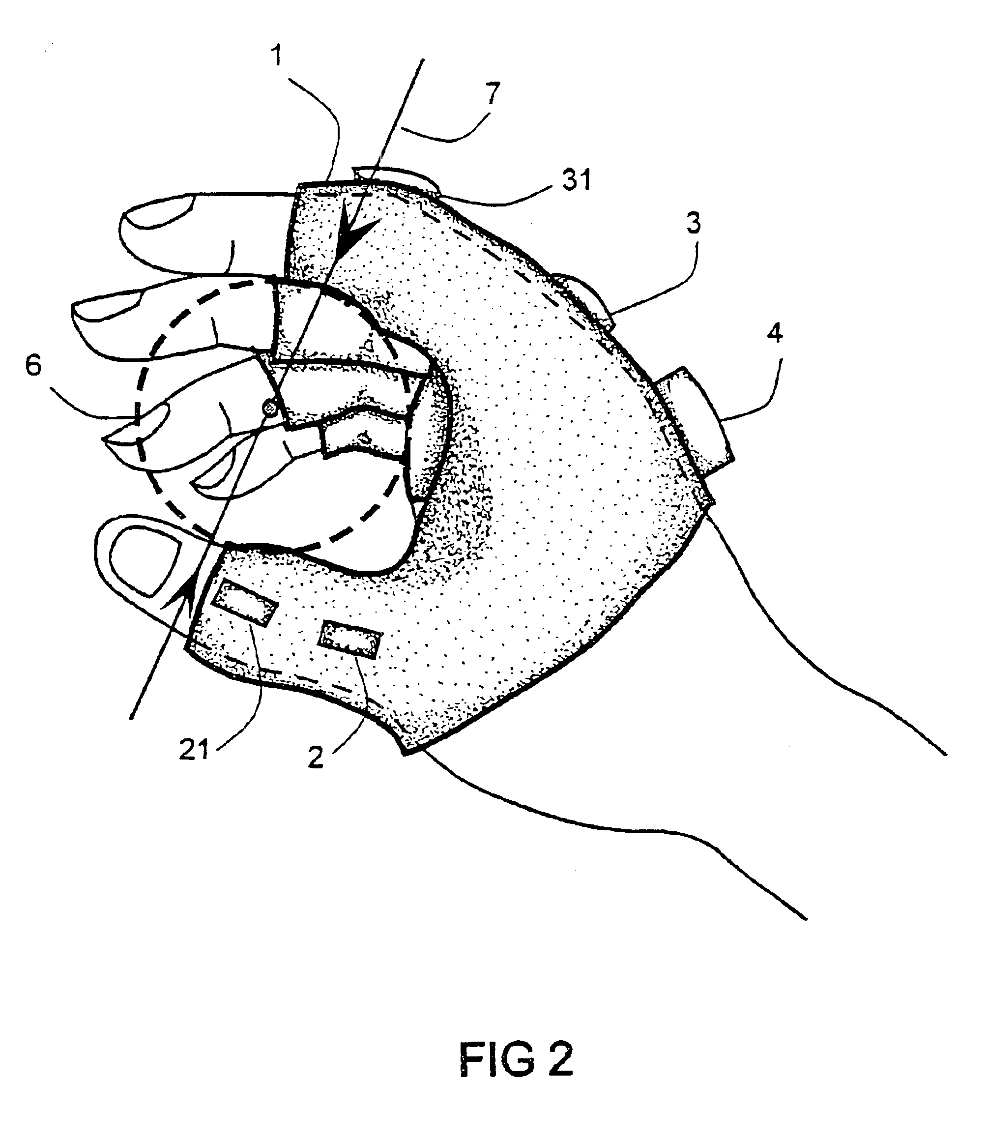
In accordance with one aspect of the present invention, there provides a mouse glove with a virtual tracking ball for cursor control of a computer, wherein the mouse glove is equipped with two pair of bending sensors mounted on the thumb and one of the other fingers said index finger and a tilt sensor mounted on the metacarpus of the user's hand. When the hand rolls, the tilt sensor on the metacarpus detects the rolling angle which determine an orientation of the direction line of the cursor movement on a computer screen. A virtual tracking ball is imagined to be held between the thumb and the index finger and the center of orientation was placed at the middle between the thumb and the index finger. The thumb is used to push the cursor from the thumb end to the center and the index finger to push from the index end to the center along the direction line, thus the bending of the thumb and the finger corresponds to the cursor movement in two opposite senses along a direction line. Each pair of the bending sensors is activated only in one bending direction with either the thumb or the finger, i.e., the inside bending to bend from an end to the center. For each pair of bending sensors, one is used for control of cursor movement on a larger scale; the other is used for adjustment of fine tuning. With such an arrangement, the control of cursor movement can be efficient and precise.

Problems solved by technology

The disadvantage of the conventional mouse is that a pad area is needed for mouse to work on.
The limitation is that the tracking ball have to be small to be mounted on a finger and the position control of a cursor appears to be unstable and lacks dexterity.
It is noted that a threshold position has to be defined for the two opposing directions to be switched ON or OFF, it is not easy to operate with that threshold in mind and the motion range of the body element for each direction is very limited.
Because the tracking ball is virtual that it can be large enough to fit just for operation of any user, and it is weightless.

Method used


Image

  • Glove mouse with virtual tracking ball
  • Glove mouse with virtual tracking ball
  • Glove mouse with virtual tracking ball

Examples


Embodiment Construction

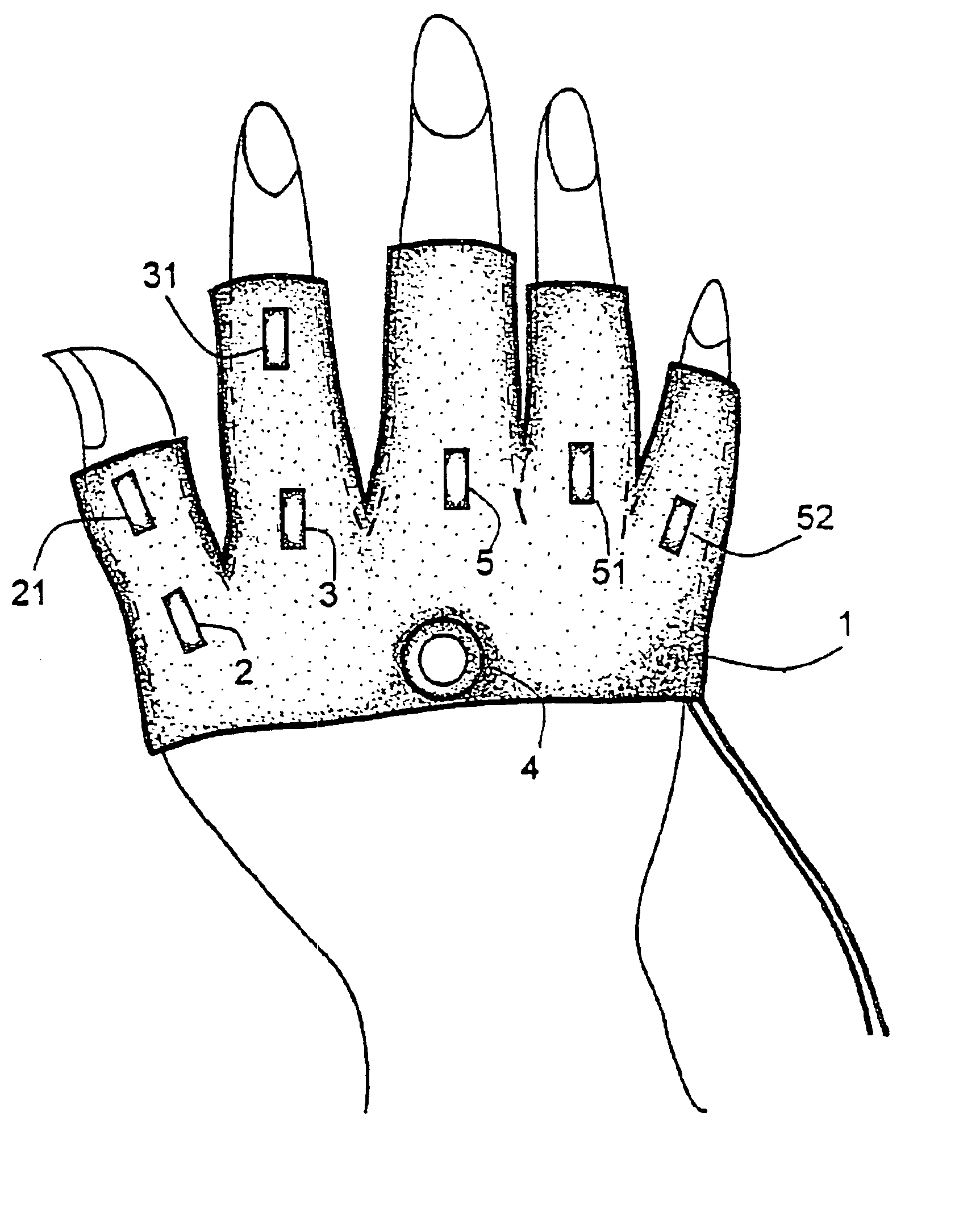
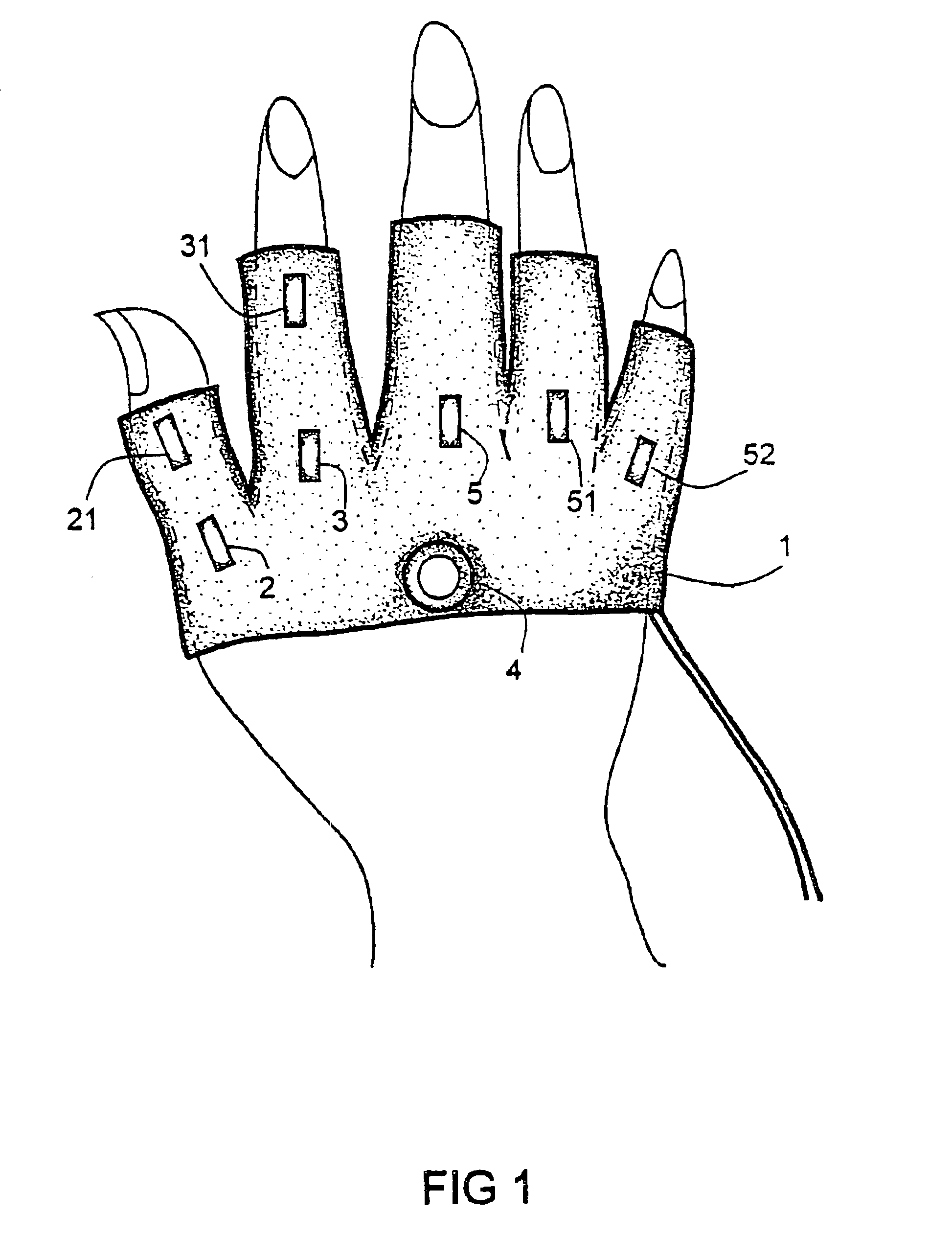
Referring to FIGS. 1 and 2, the glove mouse comprises a glove body 1 which is an apparel worn on the right hand of a computer user. The glove body 1 is equipped with two bending sensors 2 and 21 on the glove thumb, two bending sensors on the index glove finger 3 and 31, a tilt sensor 4 on the metacarpus, and three bending sensors 5, 51 and 52 on the middle finger, ring finger and little finger respectively.

In order to increase the controllability and sensitivity of the finger's bending for the control of cursor movement, two bending sensors cooperate to control the move in a single sense of direction. The bending sensors 2 and 21 mounted on the glove thumb are used to detect a bend angle change of the thumb to move the cursor along a particular direction. Each time an angle increment, which the thumb bends with, is added to the movement of the cursor as an increment to the current position. When the thumb stretches back, the increment automatically stops. The bending sensor 2 mounte...


PUM


Abstract

A glove-like apparatus mounted on a user's hand to control the cursor movement and to click for providing functions of a computer mouse. The apparatus has a glove-like body with multiple finger tubes. A tilt sensor is mounted on the glove metacarpus, of which the roll angle of the hand is detected to determine the moving orientation of the cursor. Two pairs of bending sensors are mounted on the thumb tube and the index finger tube, each pair of the sensors is used to detect a bending angle of the corresponding finger. The bending of the thumb or the index finger at a time is used to move the cursor in the negative or the positive direction along the located orientation line. The data glove for cursor control is operated as a virtual mouse with a virtual tracking ball.

Description

FIELD OF THE INVENTIONThe present invention relates to a computer mouse, and more particularly to a data glove as a virtual mouse for controlling cursor movement and click functions.BACKGROUND OF THE INVENTIONA computer mouse is an input device which the user can move over a 2D plane that the cursor on the screen will move, correspondingly. And there are two or three buttons on the mouse which allow the user to click and select. The disadvantage of the conventional mouse is that a pad area is needed for mouse to work on. Also, the user has to move his / her hand back and forth between the keyboard and the mouse frequently for word processing.Examples of apparatuses are known to relieve above drawbacks. A hand positioned mouse is disclosed by U.S. Pat. No. 6,154,199 wherein a physical tracking ball is mounted on a glove for position control of the cursor. The tracking ball is operated as the one mounted on a notebook computer except that it is mounted on the side of the index finger of...

Claims


Application Information

Patent Timeline
IPC IPC(8): G06F3/00G06F3/01
CPCG06F3/014
Inventor ZNGF, FRANKHUANG, STAN
Owner NATIONAL CHUNG HSING UNIVERSITY
Learn More