
Method and apparatus for rendering a low-resolution thumbnail image suitable for a low resolution display having a reference back to an original digital negative and an edit list of operations

a thumbnail image and low resolution technology, applied in the field of digital image processing systems, can solve the problems of not being able to know apriori, not being able to choose, and sometimes very slow operation

Inactive Publication Date: 2005-03-22
MONUMENT PEAK VENTURES LLC
View PDF17 Cites 123 Cited by
  • Summary
  • Abstract
  • Description
  • Claims
  • Application Information

AI Technical Summary

Benefits of technology

This approach significantly reduces processing time and storage needs, enables fast image download and display, and allows for efficient transmission of low-resolution images with the option to access higher resolution data when needed, improving user experience and bandwidth utilization.

Problems solved by technology

Since most imaging applications only perform image operations on one resolution, usually the highest resolution, these operations are sometimes very slow, even on the fastest computers.
While this is one option, this is not desired since it would not be possible to obtain an image rasterized at a higher resolution.
Unfortunately, it is not possible for the application to know apriori how the image will be used in the future, thus a high-resolution image is usually created.
While this appears to resolve the problems listed above, there are several limitations.
Further, the image transforms supported are limited to a few operations.
Other attempts have been made that try to remedy the problem outlined above, but with limited success.
While this does provide for efficient display of a FlashPix file over a low bandwidth network connection, it does not solve the generate problem of linking the low-resolution resultant image file back to the high-resolution digital negative and edit list.
However, it does not solve the general problem of linking the low-resolution resultant image file back to the high-resolution digital negative and edit list.
As with any of these applications, and more problematic for images, is that the size of the files could result in an almost unusable user experience when image data is transferred over low-bandwidth network connections.
Since pure peer-to-peer (no central intermediate image cache) involves direct connection between two or more end-user's computing devices, the requirement of transferring a large amount of image data, even on a high-bandwidth connection, almost makes this idea infeasible.
For photos today shared using direct peer-to-peer connections, the option is either send the high-resolution image that results in slow transmission or a low-resolution image that is faster, but poorer quality.

Method used


Image

  • Method and apparatus for rendering a low-resolution thumbnail image suitable for a low resolution display having a reference back to an original digital negative and an edit list of operations
  • Method and apparatus for rendering a low-resolution thumbnail image suitable for a low resolution display having a reference back to an original digital negative and an edit list of operations
  • Method and apparatus for rendering a low-resolution thumbnail image suitable for a low resolution display having a reference back to an original digital negative and an edit list of operations

Examples


first embodiment

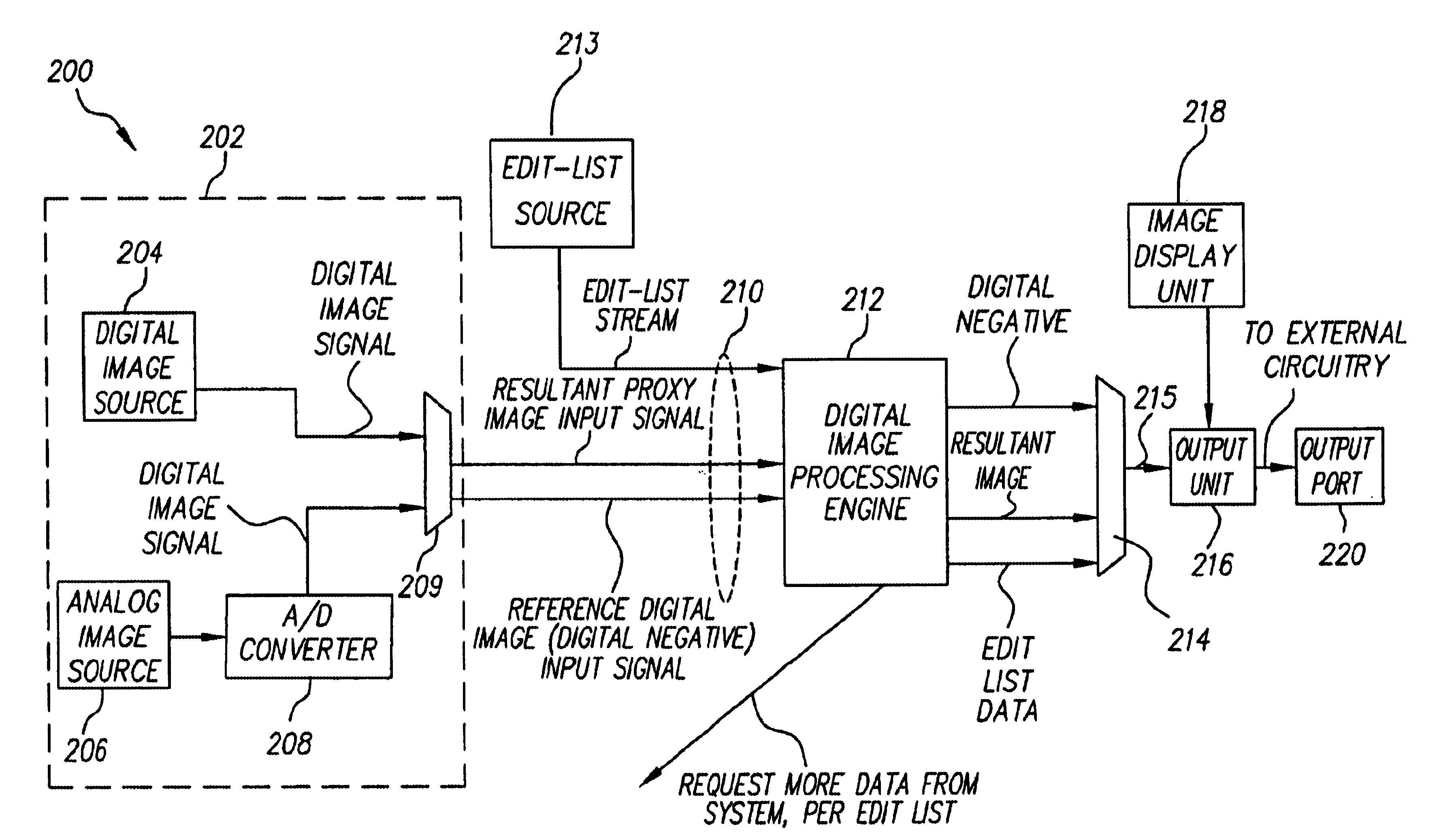
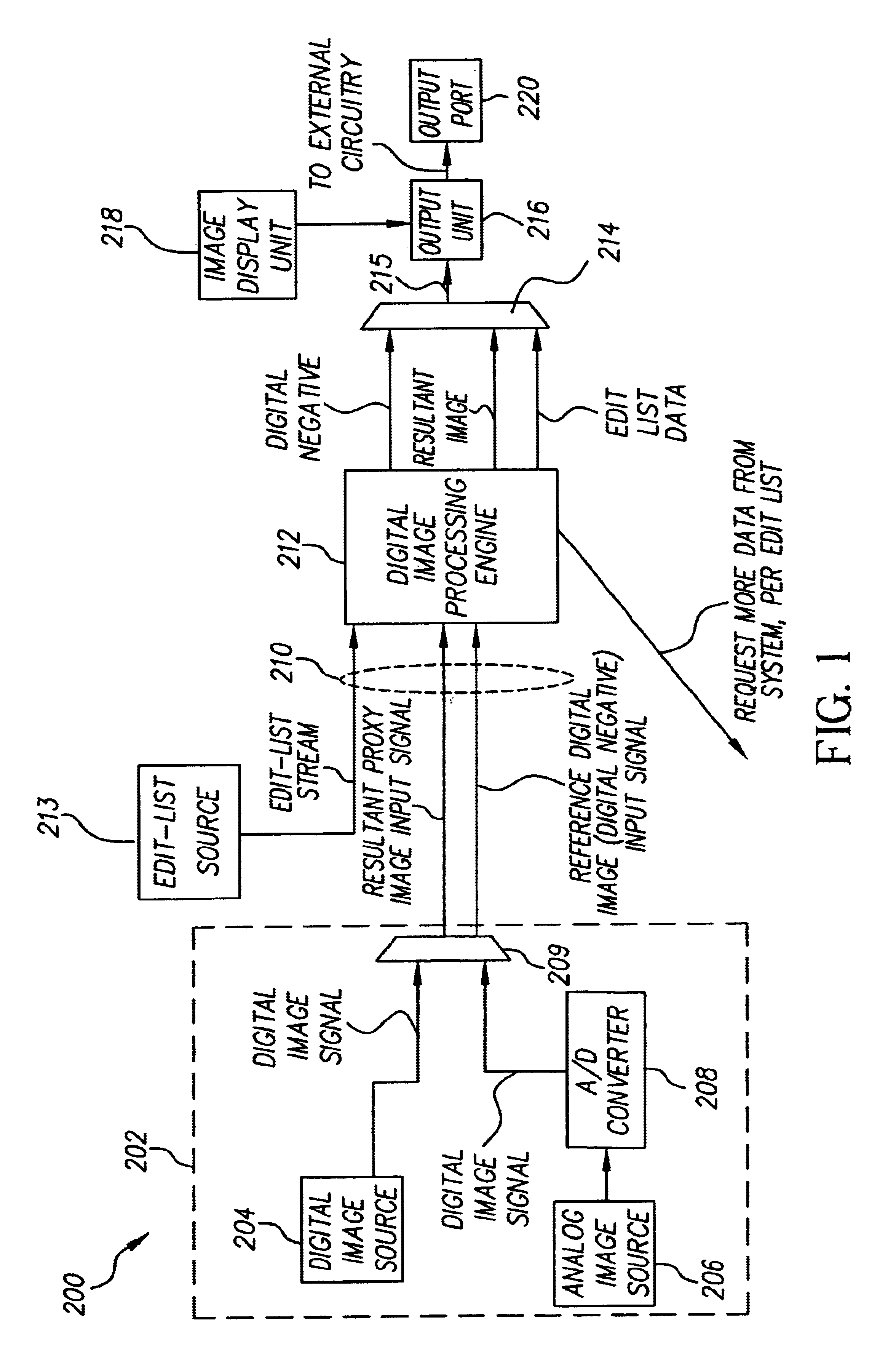
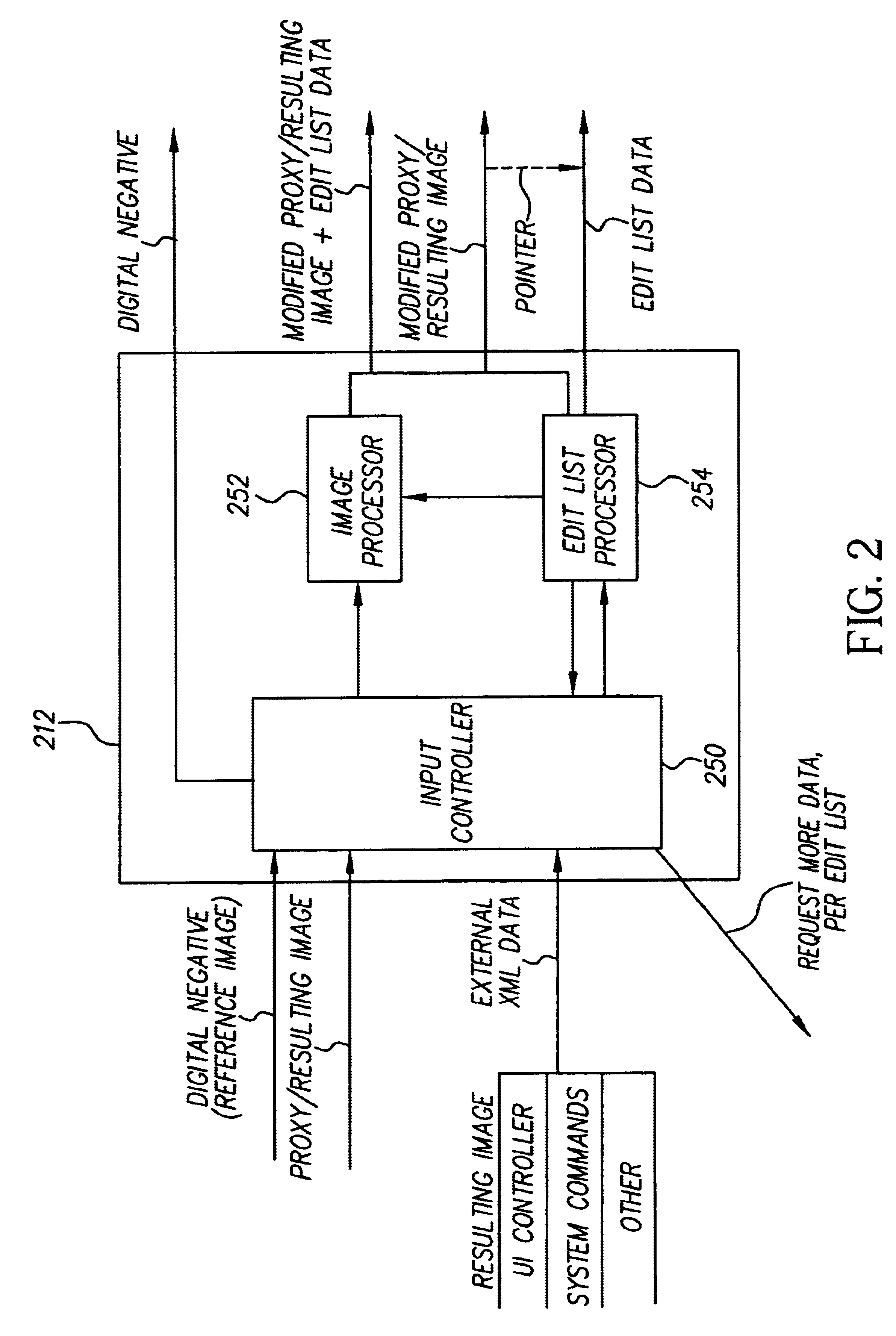
[0042]It should be realized that an “edit list ” can take the form of a variety of different embodiments, three of which are described below. This is meant to describe different variants of an edit list, but not an all-inclusive list. The first embodiment is a list that describes a set of individual operations that are to be performed on a given photo. These edit operations can be applied to a photo to generate the resultant image at the desired output resolution. The advantage of this structure is that new edits can be added to the end of the list or removed from the end of the list through an “undo” operation. A first sample piece of XML code is included for illustrative purposes:[0043][0044][0045][0046][0047][0048][0049][0050][0051]href=“www.pictureiq.com / samples / nicholas.jpg” content-type=“image / jpeg” / >[0052][0053][0054][0055][0056][0057][0058][0059][0060][0061][0062]

[0063]An alternative embodiment is to use this list to represent a state description of each operation applied to...

third embodiment

[0083]A third embodiment combines the benefits of the first two embodiments. The edit list not only represents the state description of operations, but also includes the ability for one or more of the operations that are part of the state description to be a list of individual operations that are to be applied to the photo, thus merging the two methods.

[0084]It should be noted, this architecture also allows an application to describe access to multiple resolutions of a digital negative from a single file. For example, multiple resolutions of the same image (at different resolution) could be externally linked via the “edit list” that describes the cross-reference between the various distributed image files. In this case, the “edit list” is the “glue” that holds the structure indicative of how each file is interrelated, but not necessarily the “script” that describes additional editing operations, here the “script” portion of the edit list is empty or null. For example, in one impleme...


PUM


Abstract

A method of rendering a low-resolution thumbnail image at an embedded imaging device is described. An original digital negative is captured at the embedded imaging device at an original resolution and a thumbnail digital image of the original digital negative is generated at a first resolution. The thumbnail digital image is displayed on a display device coupled to the embedded imaging device and modified to form a first resultant image at the first resolution. A first edit list based upon the modifying is generated and associated with the first resultant image and linked to the original digital negative. The linked first edit list, the original digital negative, and the first resultant image are stored at the embedded imaging device and displayed at the display device.

Description

CROSS REFERENCE TO RELATED APPLICATIONS[0002]This application claims the benefit of priority under 35 U.S.C. 119(e) of U.S. Provisional Application No. 60 / 172,301, filed Dec. 16, 1999 and entitled “TECHNIQUES FOR USING DATA ASSOCIATED WITH A DIGITAL IMAGE SUITABLE FOR RASTERIZATION AT ANY RESOLUTION ON DEMAND”, which is incorporated herein by reference in its entirety.BACKGROUND OF THE INVENTION[0003]1. Field of Invention[0004]The invention relates generally to digital image processing systems. More particularly, methods and apparatus for selectively processing a digital image are disclosed. More particularly, the invention provides techniques that for rendering a low-resolution thumbnail image suitable for a low resolution display having a reference back to an original digital negative and an edit list of operations.[0005]2. Description of Relevant Art[0006]When a user performs image operations using digital image processing programs such as Adobe Photoshop™ or PhotoDeluxe™, image ...

Claims


Application Information

Patent Timeline
Patent Type & Authority Patents(United States)
IPC IPC(8): G06F17/30
CPCG06F17/30905G06F16/9577
Inventor CROSBY, MATTWILKINS, DAVID C.
Owner MONUMENT PEAK VENTURES LLC
Learn More