Image recording apparatus and method

a technology of image recording and recording position, which is applied in the direction of thin material handling, printers, instruments, etc., can solve the problems of inability to accurately form images on photosensitive materials, inability to accurately record images, and inability to adjust the exposure position

Inactive Publication Date: 2005-03-22
FUJIFILM CORP +1
View PDF4 Cites 10 Cited by
  • Summary
  • Abstract
  • Description
  • Claims
  • Application Information

AI Technical Summary

Benefits of technology

In view of the above facts, it is an object of the present invention to provide an image recording apparatus and a method with which image formation can be accurately conducted.
According to the first aspect of the invention, the two pairs of conveyance rollers are moved into a position at which to nip the photosensitive material when at least the leading edge of the photosensitive material passes through the upstream pair of conveyance rollers. Therefore, curling of the photosensitive material reduced by the upstream pair of conveyance rollers nipping at least the leading edge of the photosensitive material. Moreover, it is possible to prevent the photosensitive material from becoming jammed in the image recording apparatus, which occurs when the photosensitive material is conveyed between the upstream pair of conveyance rollers and the downstream pair of conveyance rollers, so that the leading edge of the photosensitive material reliably advances between the downstream pair of conveyance rollers. When the leading edge of the photosensitive material has passed through the downstream pair of conveyance rollers, the two pairs of conveyance rollers are temporarily moved out of the nipping position (i.e., the two pairs of conveyance rollers temporarily release the photosensitive material) to enable edges substantially parallel to the conveyance path of the photosensitive material to be aligned in the direction substantially orthogonal to the conveyance path. After the photosensitive material has been aligned in the direction substantially orthogonal to the conveyance path, the two pairs of conveyance rollers are moved back into the nipping position to once again nip the photosensitive material at the point in time when exposure can be conducted. Thus, the accurately positioned photosensitive material is nipped between the two pairs of conveyance rollers during exposure to ensure that the photosensitive material is flat, so that an image can be accurately formed on the photosensitive material.
When the alignment section is disposed upstream from the two pairs of conveyance rollers, alignment in the direction substantially orthogonal to the conveyance path of the photosensitive material is interrupted because the pairs of conveyance rollers are moved into the nipping position when the leading edge of the photosensitive material passes through the upstream pair of conveyance rollers. For this reason, the two pairs of conveyance rollers are temporarily moved out of the nipping position (i.e., the two pairs of conveyance rollers temporarily release the photosensitive material) after the leading edge of the photosensitive material passes through the downstream pair of conveyance rollers, to thereby enable alignment of the edges of the photosensitive material in the direction substantially orthogonal to the conveyance path to be resumed and completed. Thereafter, the two pairs of conveyance rollers are moved back into the nipping position to once again nip the photosensitive material during exposure, whereby the photosensitive material is accurately positioned in the direction substantially orthogonal to the conveyance path and an image can be satisfactorily formed on the photosensitive material.
Conventionally, when the photosensitive material is long, it is not possible to correct the direction in which the photosensitive material advances if the photosensitive material has advanced obliquely and been nipped by the pairs of conveyance rollers, even if the photosensitive material is rewound. Consequently, the edges of the photosensitive material may sustain damage by being slid against guides on the direction orthogonal to the conveyance path. However, in the present invention, by allowing the pairs of conveyance rollers to release the photosensitive material (i.e., by moving the conveyance rollers out of the nipping position) when the photosensitive material is rewound, the photosensitive material is freed so that its position (direction of advancement) can be corrected and damage to the photosensitive material is avoided.
According to the second aspect of the invention, the two pairs of conveyance rollers are moved into a position at which to nip the photosensitive material when at least the leading edge of the photosensitive material passes through the upstream pair of conveyance rollers. Therefore, curling of the photosensitive material reduced by the upstream pair of conveyance rollers nipping at least the leading edge of the photosensitive material. Moreover, it is possible to prevent the photosensitive material from becoming jammed in the image recording apparatus, which occurs when the photosensitive material is conveyed between the upstream pair of conveyance rollers and the downstream pair of conveyance rollers, so that the leading edge of the photosensitive material reliably advances between the downstream pair of conveyance rollers. When the leading edge of the photosensitive material has passed through the downstream pair of conveyance rollers, the two pairs of conveyance rollers are temporarily moved out of the nipping position (i.e., the two pairs of conveyance rollers temporarily release the photosensitive material) to enable edges of the photosensitive material to be aligned in the direction substantially orthogonal to the conveyance path. After the photosensitive material has been aligned in the direction substantially orthogonal to the conveyance path, the two pairs of conveyance rollers are moved back into the nipping position to once again nip the photosensitive material at the point in time when exposure can be conducted. Thus, the accurately positioned photosensitive material is nipped between the two pairs of conveyance rollers during exposure to ensure that the photosensitive material is flat, so that an image can be accurately formed on the photosensitive material.
Conventionally, when the photosensitive material is long, it is not possible to correct the direction in which the photosensitive material advances if the photosensitive material has advanced obliquely and been nipped by the pairs of conveyance rollers, even if the photosensitive material is rewound. Consequently, the edges of the photosensitive material may sustain damage by being slid against guides on the direction orthogonal to the conveyance path. However, in the present invention, by allowing the pairs of conveyance rollers to release the photosensitive material (i.e., by moving the conveyance rollers out of the nipping position) when the photosensitive material is rewound, the photosensitive material is freed so that its position (direction of advancement) can be corrected and damage to the photosensitive material is avoided.

Problems solved by technology

However, since the lengthy photosensitive material which is wound in a roll, the photosensitive material tends to curl in the conveyance direction.
Therefore, the photosensitive material can become jammed at the exposure position when the leading edge of the photosensitive material passes through the upstream pair of conveyance rollers and proceeds between the pair of downstream conveyance rollers.
Namely, in the conventional image recording apparatus, there is a drawback that an image cannot be accurately formed on the photosensitive material.

Method used


Image

  • Image recording apparatus and method
  • Image recording apparatus and method
  • Image recording apparatus and method

Examples


Embodiment Construction

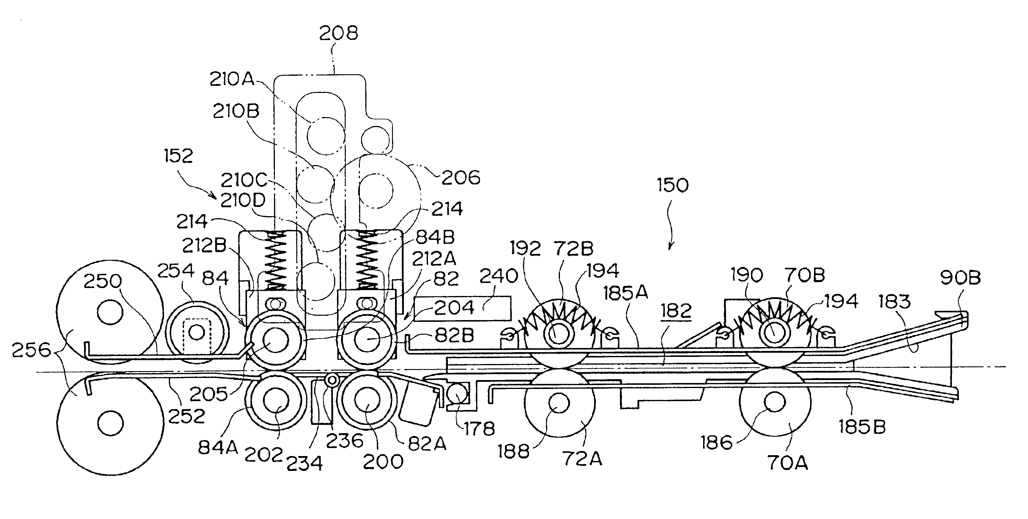
Hereinafter, an image recording apparatus and a method of the present invention will be described in detail on the basis of a preferred embodiment shown in attached drawings. First, the overall structure of the image recording apparatus will be described, and then two pairs of nip (conveyance) rollers will be described.

Overall Structure of Image Recording Apparatus

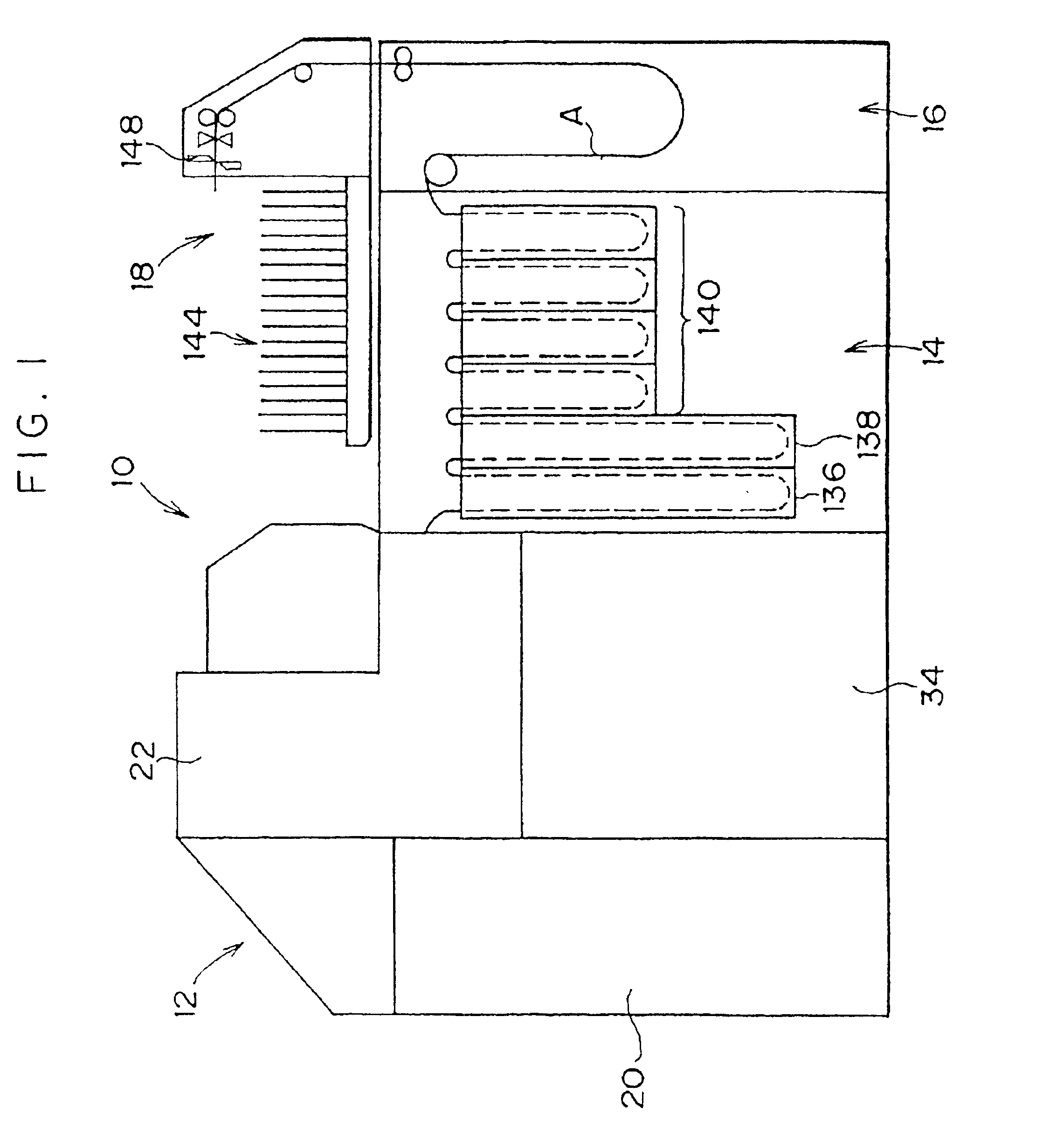
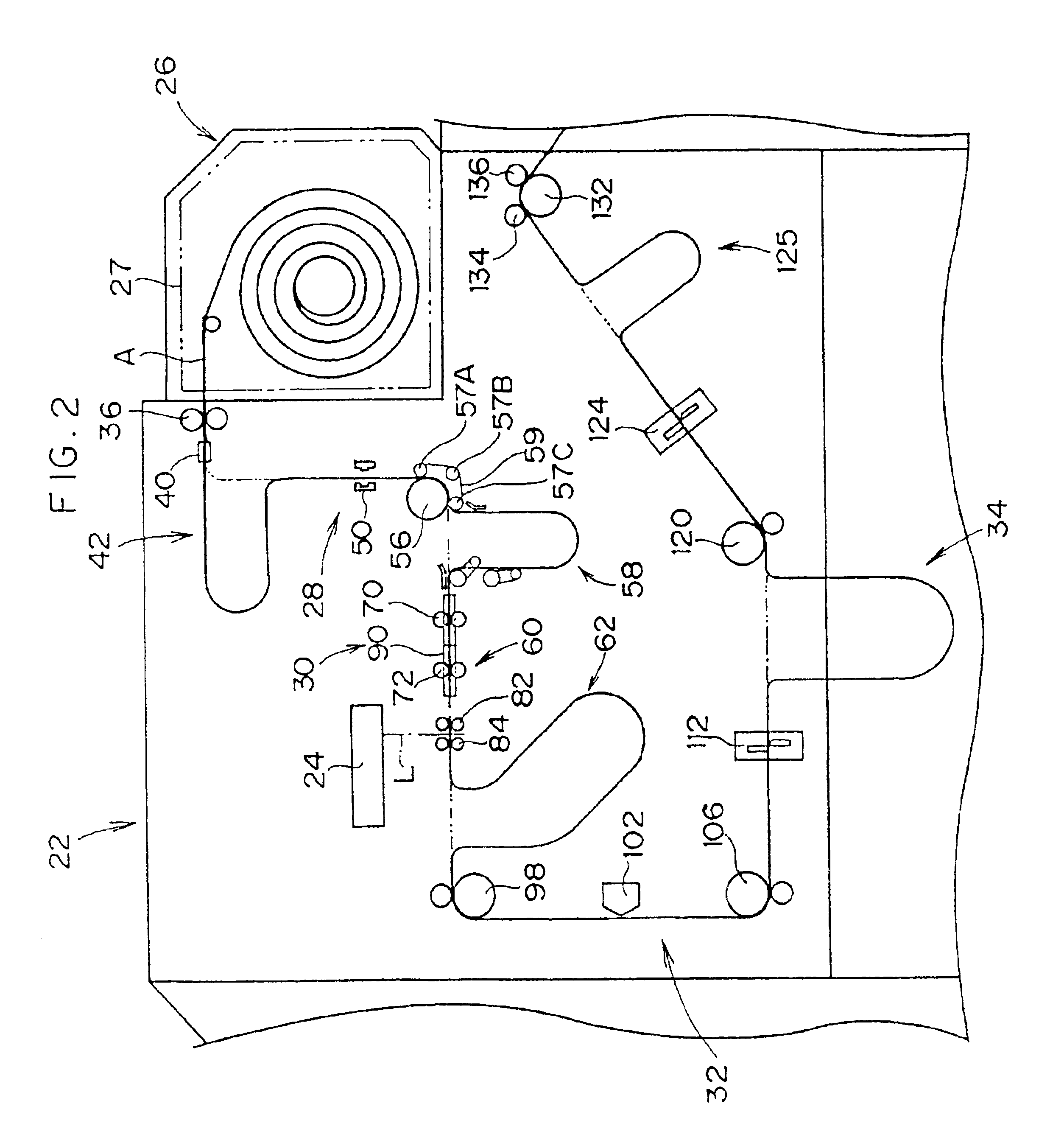
FIG. 1 illustrates an image recording apparatus 10 that is mainly used in a digital photoprinter. The image recording apparatus 10 scan-exposes a photosensitive material A with a light beam to form a latent image, based on exposure conditions (image recording conditions) which have been determined by a setup apparatus in accordance with an image read by an image reading apparatus such as a film scanner, develops and processes the photosensitive material A, and outputs a print on which the image on the film is recorded. The image recording apparatus 10 basically comprises an image recording section 12, a developing section ...


PUM


Abstract

An image recording apparatus for exposing a photosensitive material includes two pairs of nip rollers. One pair of nip rollers is disposed upstream from a position at which the photosensitive material is exposed, and the other pair of nip rollers is disposed downstream from the exposure position. When a leading edge of the photosensitive material passes through the upstream pair of nip rollers, both pairs of nip rollers are moved into a position at which to nip the photosensitive material to prevent the photosensitive material from becoming jammed. When the leading edge of the photosensitive material passes through the downstream pair of nip rollers, the pairs of nip rollers are moved out of the nipping position to allow edges substantially parallel to a conveyance path of the photosensitive material to be aligned in the direction substantially orthogonal to the conveyance path.

Description

BACKGROUND OF THE INVENTION1. Field of the InventionThe present invention relates to an image recording apparatus and a method in which a photosensitive material is exposed to form an image thereon.2. Description of the Related ArtIn recent years, digital photoprinters have been practically utilized as printing apparatus that utilize digital exposure. In a printing apparatus, initially, an image recorded on a film is photoelectrically read and the read image is converted to a digital signal. Thereafter, the image that has been converted to the digital signal is subjected to various image processing, whereby image data for recording is generated. A photosensitive material is then scan-exposed with recording light modulated in accordance with the image data to record the image (latent image) on the photosensitive material. Finally, the photosensitive material is developed and processed, and outputted as a print (photograph).In a digital photoprinter, an image recorded on a film is pho...

Claims


Application Information

Patent Timeline
Patent Type & Authority Patents(United States)
IPC IPC(8): G03B27/32H04N1/12B65H20/02G03B27/46
CPCG03B27/32H04N1/00676H04N1/00705H04N1/123H04N1/0079H04N1/121H04N1/00745
Inventor YAMADA, NAOTO
Owner FUJIFILM CORP
Why Eureka
Try Eureka