

Progressive/interlace and redundant field detection for encoder
- Summary
- Abstract
- Description
- Claims
- Application Information
AI Technical Summary
Problems solved by technology
Method used
Image

Examples
Embodiment Construction
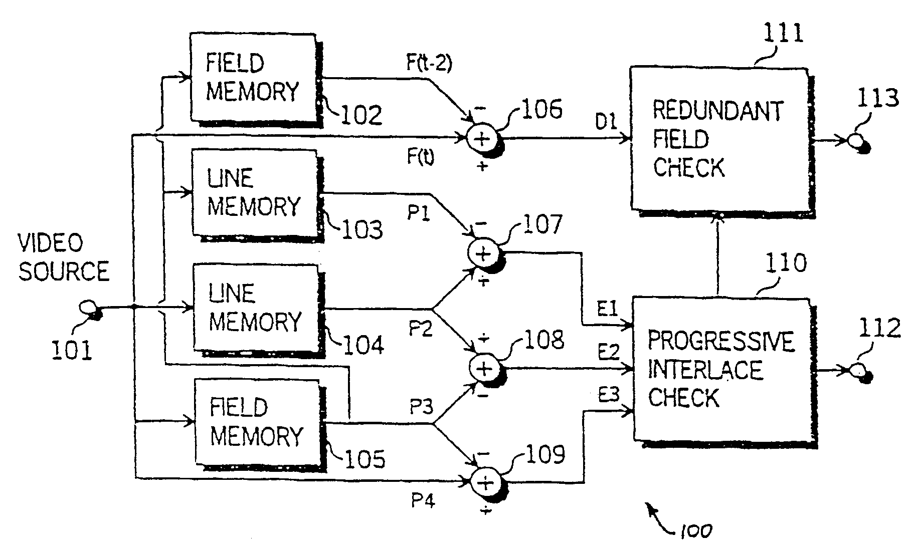
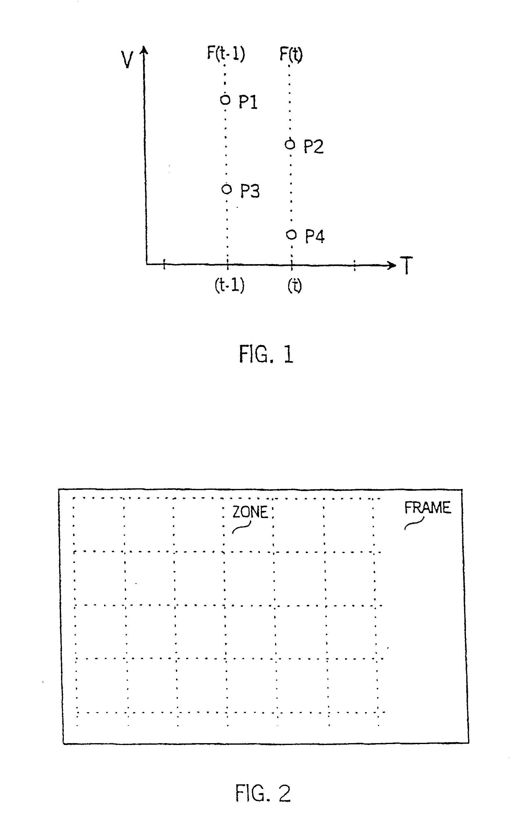
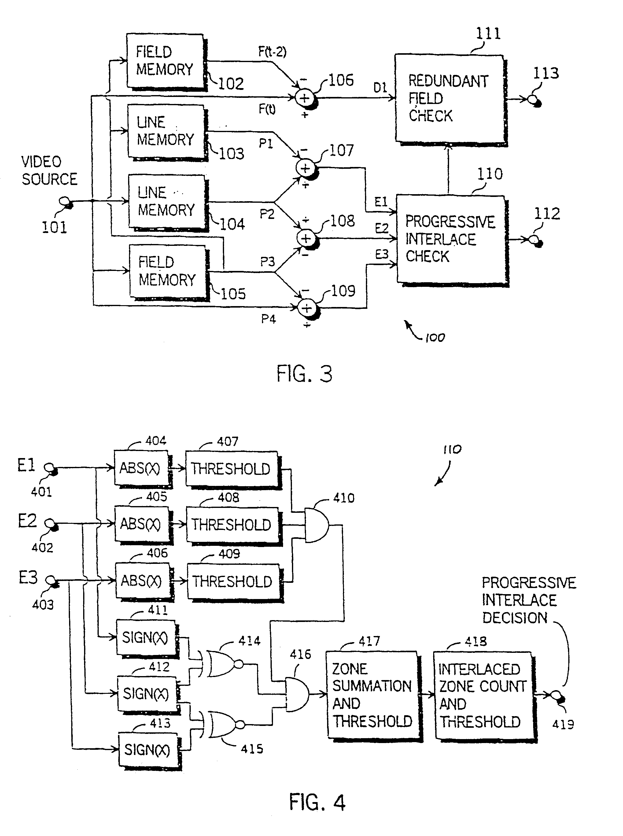
A progressive / interlace and redundant field detector 100, as shown in FIG. 3, characterises an interlace pattern as being an object area with high inter-field differences, which is detected using four vertically adjacent luminance pixels from two successive fields from a video source. FIG. 1 illustrates an example of four luminance pixels for use in interlace pattern detection in a vertical / temporal plane. The pixels are labelled P1 to P4, wherein pixels P1 and P3 are obtained from a field F(t−1) at time (t−1) and pixels P2 and P4 are sampled from a field F(t) at time t. The differences between vertically adjacent pixels are obtained and compared to a threshold (T1) according to the following pseudo-code for interlace pattern detection:
if {(P1-P2)>T1 and (P3−P2)>T1 and (P3−P4)>T1}
or {(P2−P1)>T1 and (P2-P3)>T1 and (P4−P3)>T1}
interlace pattern detected.
The two successive fields are determined as interlaced if there are sufficient areas within the two fields containing interlace patter...
PUM
 Abstract
Description
Claims
Application Information