Electrochromic rearview mirror element incorporating a third surface reflector

a technology of rearview mirror and surface reflector, which is applied in non-linear optics, instruments, transportation and packaging, etc., can solve the problems of not having sufficient reflectivity, not having stable, and no group had commercial success

Inactive Publication Date: 2005-03-22
GENTEX CORP
View PDF60 Cites 273 Cited by
  • Summary
  • Abstract
  • Description
  • Claims
  • Application Information

AI Technical Summary

Benefits of technology

[0025]Another aspect of the present invention is to provide an exterior rearview mirror assembly incorporating a light source for illuminating a portion of the exterior of the vehicle, such as the door handle and locking mechanism area of a vehicle door. To achieve these and other aspects and advantages, an exterior rearview mirror assembly of the present invention comprises a housing adapted to be mounted to the exterior of the vehicle; a first element mounted in the housing, the element having a front and rear surface; a reflector disposed on one of the surfaces of the first element; and a light source mounted in the housing behind the rear surface of the first element, the light source being positioned within the housing so as to emit light, when activated, through the first element and through a region of the reflector that is at least partially transmissive toward a side of a vehicle. Such a rearview mirror assembly thus conveniently illuminates areas on the outside of the vehicle such as the door handles and locking mechanisms.

Problems solved by technology

Although this concept was described as early as 1966, no group had commercial success because of the exacting criteria demanded from a workable auto-dimming mirror incorporating a third surface reflector.
Although a third surface reflector is discussed therein, the materials listed as being useful as a third surface reflector suffer from one or more of the following deficiencies: not having sufficient reflectivity for use as an inside mirror, or not being stable when in contact with a solution-phase electrochromic medium containing at least one solution-phase electrochromic material.
Although this design works adequately due to the transparent conductors on the second and third surface to impart current to the electrochromic medium, presently no design is commercially available which allows a display device to be incorporated into a mirror that has a reflective layer on the third surface.
Removing all of the reflective layer on the third surface in the area aligned with the display area or the glare sensor area causes severe residual color problems when the electrochromic medium darkens and clears because, although colorization occurs at the transparent electrode on the second surface, there is no corresponding electrode on the third surface in that corresponding area to balance the charge.
This color variation is significant and is very aesthetically unappealing to the vehicle occupants.
Similar problems exist for outside rearview mirror assemblies that include signal lights, such as turn signal lights, behind the rear surface of the mirror.

Method used


Image

  • Electrochromic rearview mirror element incorporating a third surface reflector
  • Electrochromic rearview mirror element incorporating a third surface reflector
  • Electrochromic rearview mirror element incorporating a third surface reflector

Examples


example 1

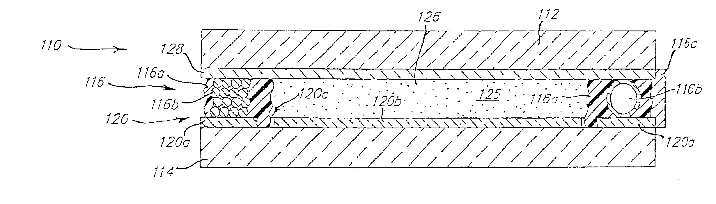
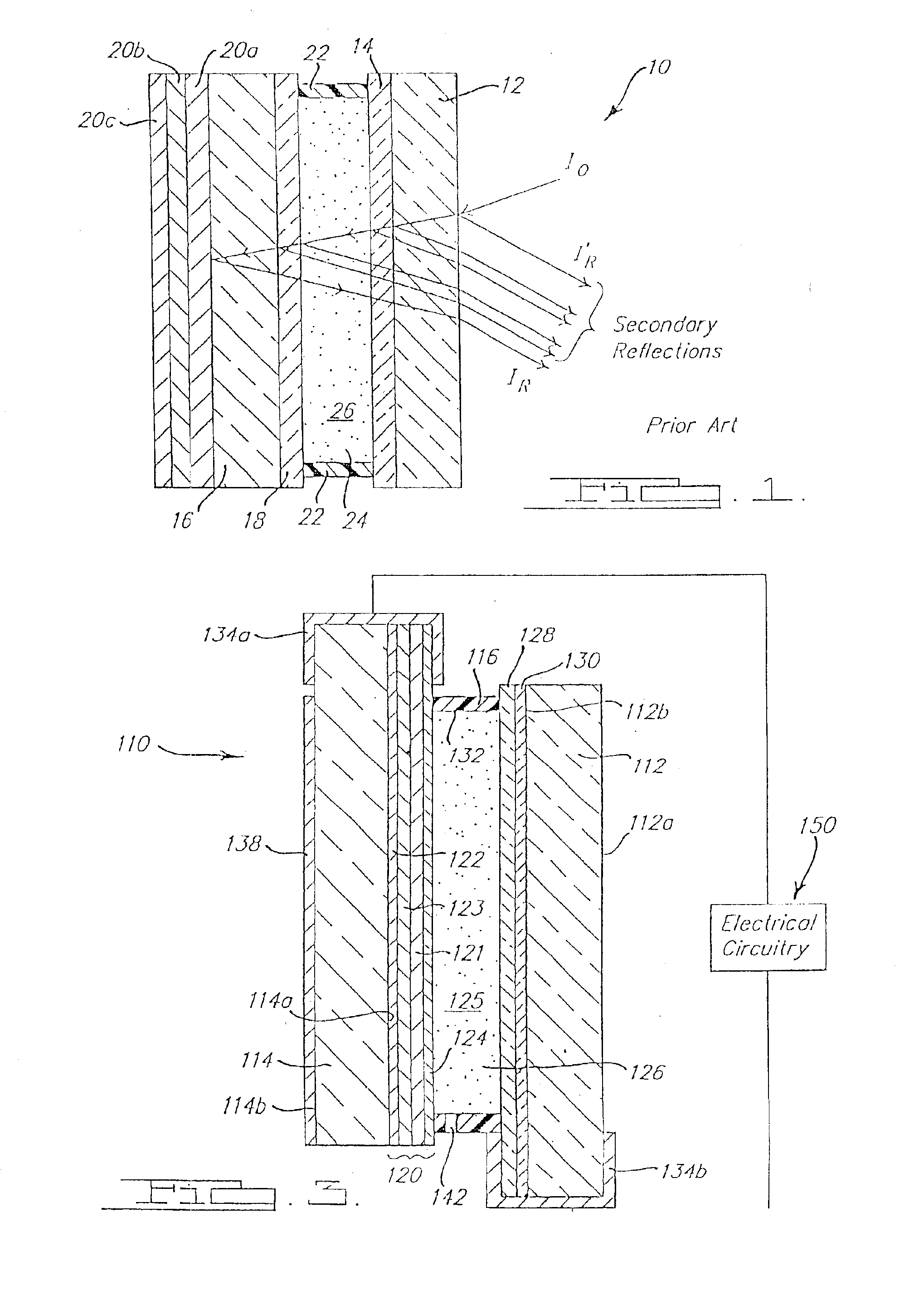
[0098]Electrochromic mirror devices incorporating a high reflectivity third surface reflector / electrode were prepared by sequentially depositing approximately 700 Å of chromium and approximately 500 Å of silver on the surface of 2.3-mm thick sheets of flat soda lime float glass cut to an automotive mirror element shape. A second set of high reflectivity third surface reflector / electrodes were also prepared by sequentially depositing 700 Å of chromium and approximately 500 Å of a silver alloy containing 3 percent by weight palladium on the glass element shapes. The deposition was accomplished by passing the said glass element shapes past separate metal targets in a magnetron sputtering system with a base pressure of 3×10⁻⁶ torr and an argon pressure of 3×10⁻³ torr.

[0099]The chromium / silver and chromium / silver 3 percent palladium alloy coated glass automotive mirror shapes were used as the rear planar elements of an electrochromic mirror device. The front element was a sheet of TEC 15...

example 2

[0105]Other than as specifically mentioned, the devices in this example were constructed in accordance with the conditions and teachings in Example 1. Multilayer combination reflector / electrodes were prepared by sequentially depositing approximately 700 Å chromium, approximately 100 Å rhodium, and approximately 500 Å of silver on the surface of the glass element shapes. A second set of multilayer combination reflector / electrodes were also prepared by sequentially depositing approximately 700 Å of chromium, approximately 100 Å rhodium, and approximately 500 Å of a silver alloy containing 3 percent by weight palladium on the surface of said glass element shapes. The electrochromic devices were constructed and tested in accordance with Example 1.

[0106]The device incorporating the sequential multilayer combination reflector electrode of chromium, rhodium, and silver withstood steam autoclave testing two times longer and CASS testing 10 times longer than the device in Example 1 before fa...

example 3

[0107]Other than as specifically mentioned, the devices in this example were constructed in accordance with the conditions and teachings in Example 1. Multilayer combination reflector / electrodes were prepared by sequentially depositing approximately 700 Å chromium, approximately 500 Å molybdenum and approximately 500 Å of a silver alloy containing 3 percent by weight palladium on the surface of said glass element shapes. The electrochromic devices were constructed and tested in accordance with Example 1.

[0108]The device incorporating the sequential multilayer combination reflector electrode of chromium, molybdenum, and silver 3 percent palladium alloy withstood CASS testing 10 times longer than devices in Example 1 before failure occurred.


PUM

PropertyMeasurementUnit
reflectivityaaaaaaaaaa
transmittanceaaaaaaaaaa

Abstract

The inventive electrochromic mirror may be used in a vehicle rearview mirror assembly having a light source positioned behind the electrochromic mirror for selectively projecting light through the mirror. The electrochromic mirror includes front and rear spaced elements each having front and rear surfaces and being sealably bonded together in a spaced-apart relationship to define a chamber, a layer of transparent conductive material disposed on the rear surface of the front element, an electrochromic material is contained within the chamber, and a second electrode overlies the front surface of the rear element in contact with the electrochromic material. The second electrode includes a layer of reflective material and a partially transmissive coating of and is disposed over substantially all of the front surface of the rear element. The second electrode further includes a region in front of the light source that is at least partially transmissive.

Description

CROSS-REFERENCE TO RELATED APPLICATIONS[0002]This application is a continuation of U.S. patent application Ser. No. 09 / 994,218, filed on Nov. 26, 2001, entitled “ELECTROCHROMIC REARVIEW MIRROR INCORPORATING A THIRD SURFACE PARTIALLY TRANSMISSIVE REFLECTOR,” by William L. Tonar et al., now U.S. Pat. No. 6,512,624; which is a continuation of U.S. patent application Ser. No. 09 / 311,955, filed on May 14, 1999, entitled “ELECTROCHROMIC REARVIEW MIRROR INCORPORATING A THIRD SURFACE METAL REFLECTOR AND A DISPLAY / SIGNAL LIGHT,” by William L. Tonar et al., now U.S. Pat. No. 6,356,376; which is a continuation-in-part of U.S. patent application Ser. No. 09 / 206,788, filed on Dec. 7, 1998, entitled “ELECTROCHROMIC REARVIEW MIRROR INCORPORATING A THIRD SURFACE METAL REFLECTOR AND A DISPLAY / SIGNAL LIGHT,” by William L. Tonar et al., now U.S. Pat. No. 6,166,848; which is a continuation-in-part of U.S. patent application Ser. No. 09 / 197,400, filed on Nov. 20, 1998, entitled “ELECTROCHROMIC REARVIEW ...

Claims


Application Information

Patent Timeline
Patent Type & Authority Patents(United States)
IPC IPC(8): B60R1/12B60Q1/26B60R1/08G02F1/01G02F1/153G02F1/155G02F1/157G02F1/15H01L51/52H01L51/50G02B5/00B60R1/04B60R1/06G02B1/10G02B5/02G02B5/08G02B5/10G02B27/00G02B27/01G02F1/1506H01L33/44H01L33/46H01L33/48H01L33/58
CPCB60Q1/2665B60R1/1207G02B27/01G02F1/1533G02F1/155G02F1/157B60R1/088H01L51/529B60R2001/1215B60R2001/1223G02B5/02G02B2027/0112G02B2027/0114G02B2027/012G02F1/1506G02F2001/1502G02F2001/1512G02F2201/34G02F2203/02G02F2001/15145H10K50/87
Inventor TONAR, WILLIAM L.FORGETTE, JEFFREY A.ANDERSON, JOHN S.BECHTEL, JON H.CARTER, JOHN W.STAM, JOSEPH S.CAMMENGA, DAVID J.
Owner GENTEX CORP
Why Eureka
Try Eureka