Device for exchanging radio signals provided with time markers for synchronizing clocks

Inactive Publication Date: 2005-03-22
THOMSON CSF DETEXIS
View PDF6 Cites 10 Cited by
  • Summary
  • Abstract
  • Description
  • Claims
  • Application Information

AI Technical Summary

Benefits of technology

The present invention improves the situation. It starts from a device comprising radio transmission/reception means, to which there are coupled on the o

Problems solved by technology

In addition, the transmission medium is rarely perfect, and often dispersive.
In particular, in the case of an earth-satellite transmission, strong interference is observed when passing through the ionosphere and troposphere.
However, this poses problems, notably with regard to the allocation of frequencies.
However, this implies shared time, always tricky because of the risk of interference.
In addition,

Method used


Image

  • Device for exchanging radio signals provided with time markers for synchronizing clocks
  • Device for exchanging radio signals provided with time markers for synchronizing clocks
  • Device for exchanging radio signals provided with time markers for synchronizing clocks

Examples


Embodiment Construction

The following detailed description and the drawings related thereto contain essentially elements of a certain character. The drawings can therefore not only serve to give a better understanding of the invention but also contribute to its definition, where necessary.

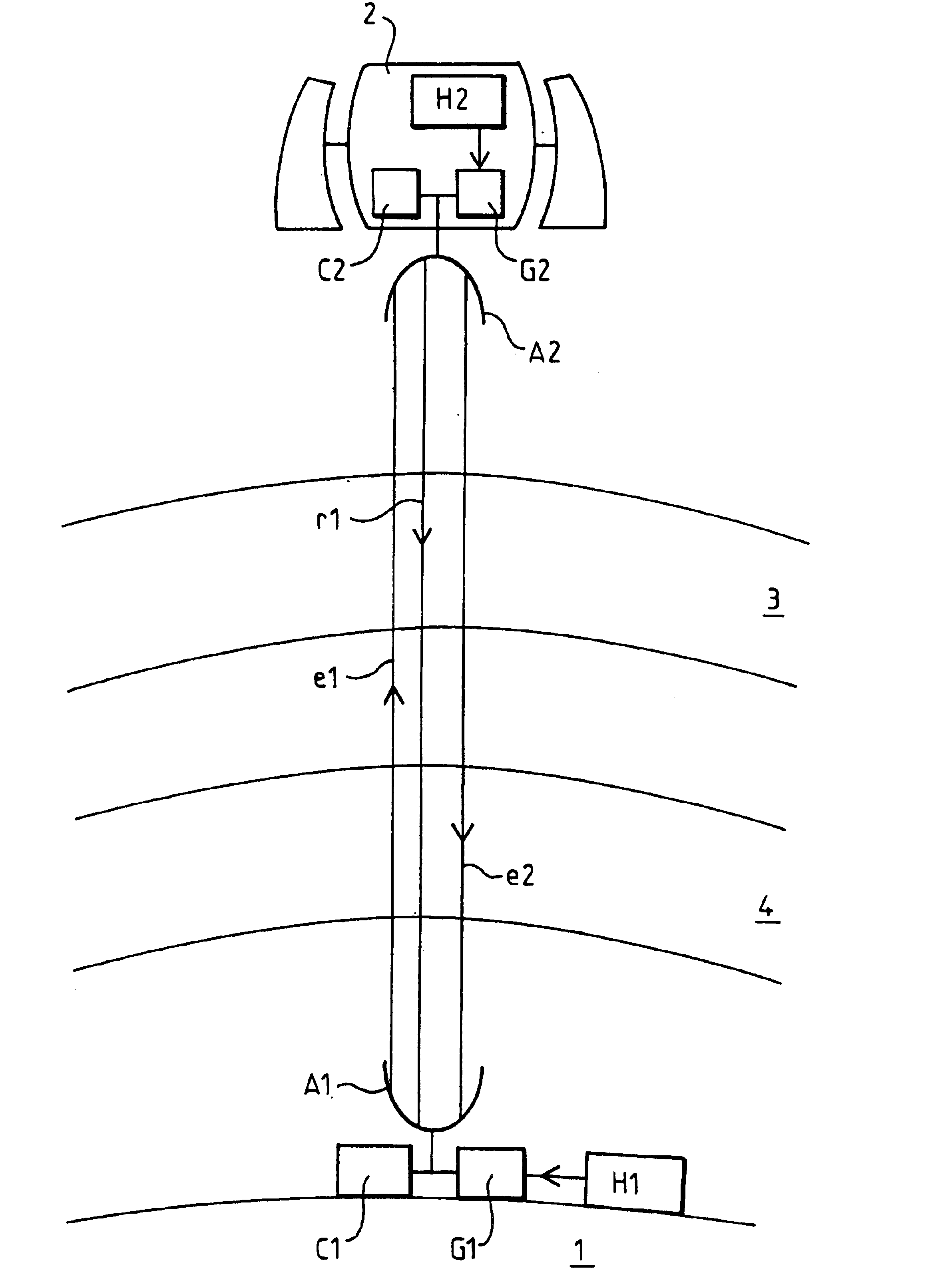
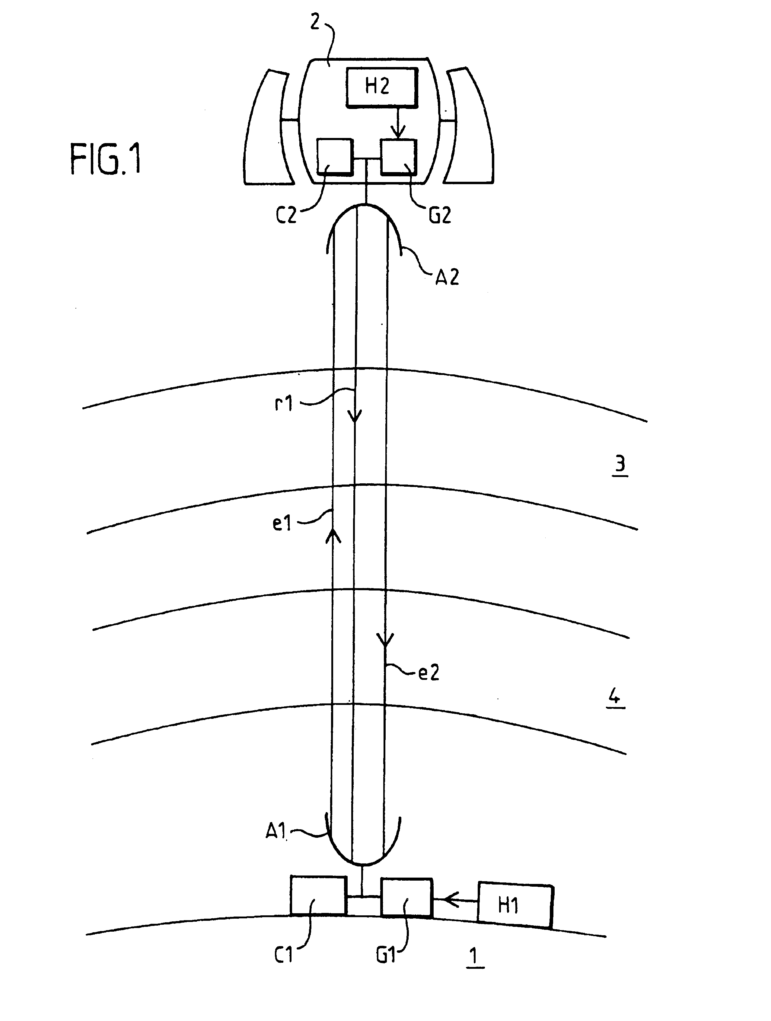
It is considered hereinafter that the device according to the invention is applied to the precise measurement of a time difference between two distant atomic clocks. The precision required for this measurement is around 1 picosecond. The two atomic clocks H1 and H2 are for example cooled caesium clocks.

As shown in FIG. 1, the clock H2 is on board a satellite 2 in low orbit. The other clock H1 is on the ground. This is the context of the experiment on a satellite known as “alpha station”.

Conventionally, the measurement of the difference between a distant clock and a local clock is effected optically. A pulsed laser beam is used, generally with a wavelength of around 532 nanometers. However, the absorption and diffusion of ...


PUM


Abstract

Radio transmission of chronometric information. A device comprising an antenna (A1, A2) to which there are coupled on one hand a generator (G1, G2) generating a signal to be sent (e1, e2) and a reception processing circuit (C1, C2), capable of processing a received signal (r1, e2) where the signals exchanged have the same carrier frequency. Separate time segments are generated with successive random positions. Transmission is enabled only during these time segments, whilst reception is enabled only outside these segments, making it possible to use the time markers of the signals without any effect of recurrent masking of the reception signal by the transmission signal.

Description

BACKGROUND OF THE INVENTIONThe invention concerns apparatus and methods for the radio transmission of chronometric information.In order to transmit chronometric pips by radio, use is normally made of a carrier wave provided with a repetitive pattern forming a time marker, equivalent to a brief pulse. The time marker is for example a code of the pseudo-random or “pseudo-noise” type.It is advantageous to apply this technique to the synchronization of very precise clocks, one being situated for example on the ground and the other on board a satellite. It is a case of precisely measuring the time difference between the respective transitions of these atomic clocks. More generally, it is a case of seeking the time difference between two contemporary events occurring in stations which are distant in space, the word “station” not implying a stationary position here.One of the stations transmits to the other a time marker related to its own event. Subject to knowing the actual transit time ...

Claims


Application Information

Patent Timeline
IPC IPC(8): H04B7/212
CPCH04B7/2125
Inventor POTIER, THIERRY
Owner THOMSON CSF DETEXIS
Why Eureka
Try Eureka