Method and apparatus for use in specifying and insuring service-level quality of service in computer networks

a computer network and service level technology, applied in the field of computer network, can solve the problems of difficult or impossible for clients without network management expertise to express the desired system behavior, and achieve the effects of reducing network resources, facilitating parameters, and increasing network resources assigned

Inactive Publication Date: 2005-03-22
LUCENT TECH INC
View PDF21 Cites 64 Cited by
  • Summary
  • Abstract
  • Description
  • Claims
  • Application Information

AI Technical Summary

Benefits of technology

Specifically, one embodiment of the invention employs a management server including a graphical interface that allows a user, e.g. an administrator, to easily specify parameters for predefined types of service-level QoS goals. A QoS goal is defined by specifying a client, a service, and a QoS expression. A QoS expression is a proposition that indicates the client's desired range of values for some QoS metric, e.g. service response time or service availability. The state of the network is monitored and one or more defined QoS goals are selected for evaluation in a continuous process. The QoS delivered f

Problems solved by technology

This makes it difficult or impossible for clients without expertise in network manageme

Method used


Image

  • Method and apparatus for use in specifying and insuring service-level quality of service in computer networks
  • Method and apparatus for use in specifying and insuring service-level quality of service in computer networks
  • Method and apparatus for use in specifying and insuring service-level quality of service in computer networks

Examples


Embodiment Construction

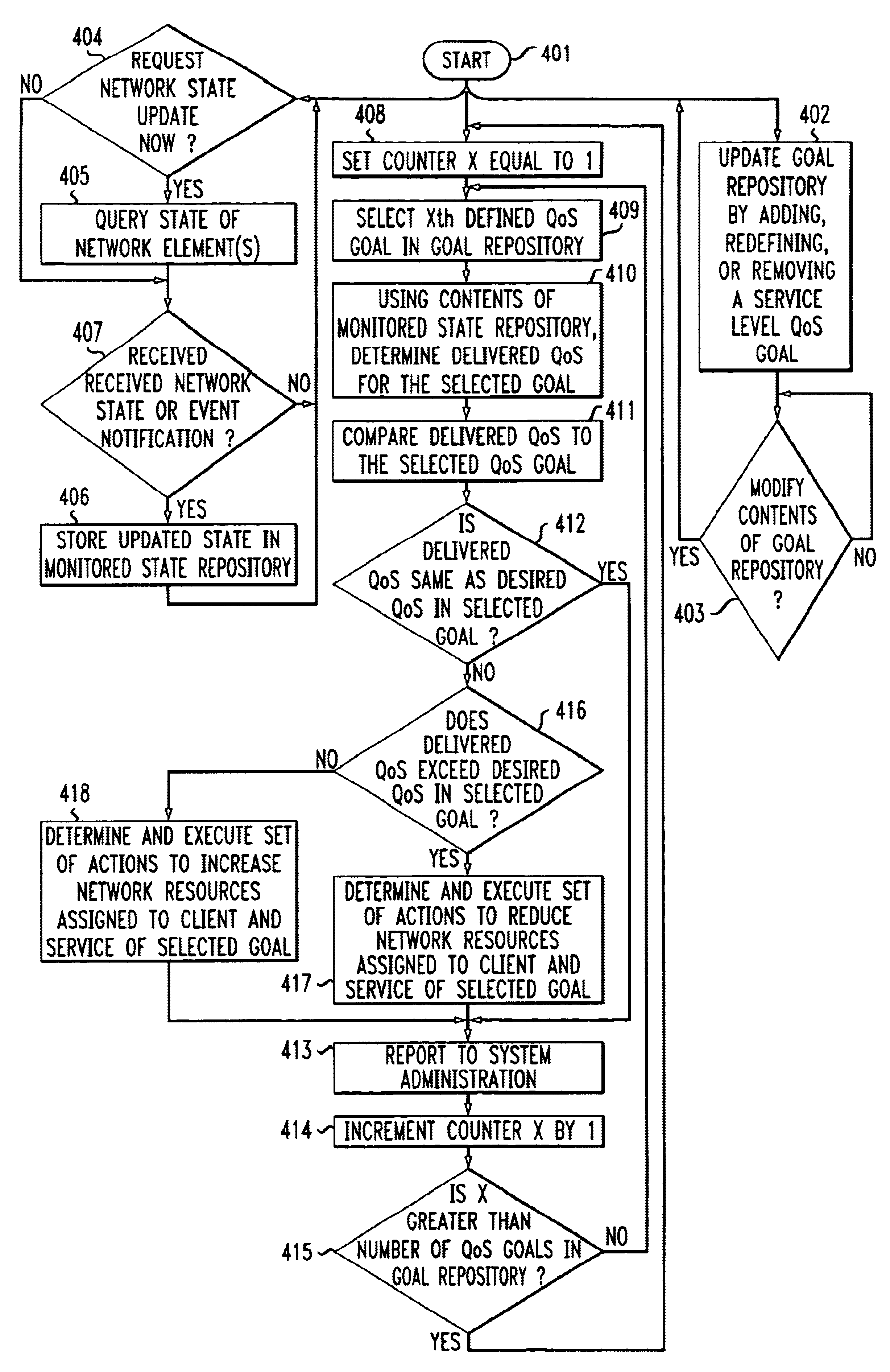
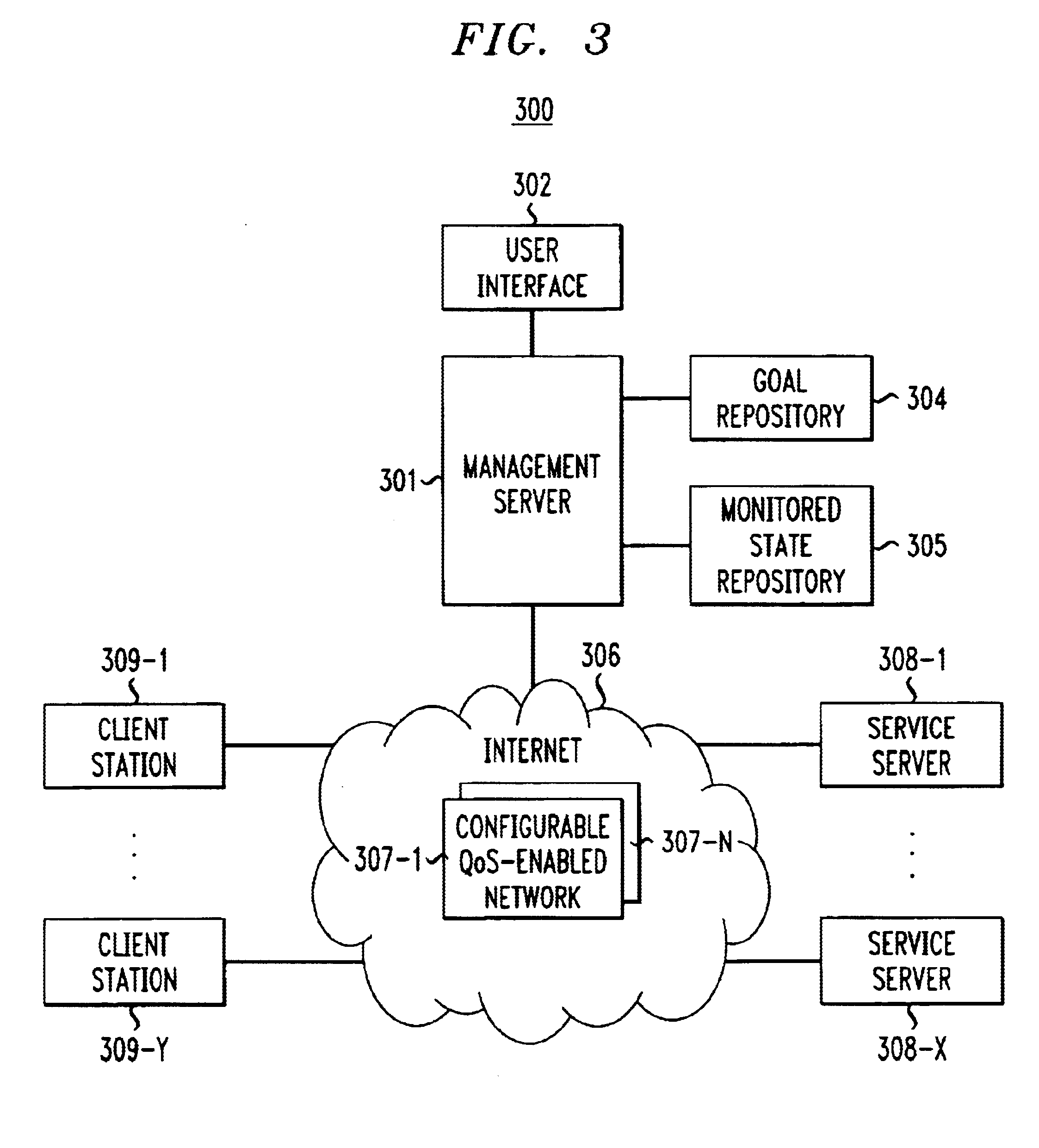
Again, it is noted that current PBM arrangements require system administrators to specify rules that to the system administrator represent the specification of “what” needs to be achieved in terms of network / system behavior. From a client viewpoint, however, these rules represent the “how” of management. The client is really interested in service-level QoS goals such as “my transaction failure rate should be less than some specific value” or “my end-to-end response should be less than some specific value”. Indeed, there is currently no support in prior arrangements for specifying the client's service-level QoS goals as part of the management policy definition.

FIG. 1 is a table illustrating in simplified form example QoS goals. As shown, QoS goals are represented using the generalized goal template shown in TABLE 1, namely, “during T, satisfy Q for client C that uses service S”. The goal parameters, in this example, are defined as follows. Parameters C and S identify respectively a c...


PUM


Abstract

The “what” and “how” of policy-based management is integrated in a single framework that enables a system administrator to specify service-level quality of service (QoS) goals for automatic enforcement. Automatic enforcement of the specified “high-level” QoS goals is realized through the execution of “low-level” rule-based or procedural logic, without the client having to specify the low level logic. Specifically, one embodiment of the invention employs a management server including a graphical interface that allows a user, e.g. a system administrator, to easily specify parameters for service-level QoS goals. A QoS goal is defined by the administrator selecting a client, a service and a QoS expression that specifies the desired service-level QoS. The state of the network is monitored and one or more defined QoS goals are selected for evaluation in a continuous process. The QoS delivered for the selected goal is determined and compared to the desired QoS for the selected QoS goal. Then, prescribed actions are taken or not depending whether the delivered QoS is equal to the selected QoS goal. If not, and the delivered QoS exceeds the selected QoS goal, a set of actions is determined and executed to reduce network resources assigned to the client and service of the selected goal. Similarly, if the delivered QoS is worse than the selected QoS goal, a set of actions is determined and executed to increase network resources assigned to the client and service of the selected goal.

Description

RELATED APPLICATIONUnited States patent application Ser. No. 09 / 610,631 was filed concurrently herewith.TECHNICAL FIELDThis invention relates to computer networks and, more particularly, to monitoring and controlling quality of service (QoS) in such computer networks.BACKGROUND OF THE INVENTIONKnown policy-based computer network management arrangements do not clearly distinguish the goal, i.e. the “what”, of management from the policy, i.e. the “how”, that achieves the goal. Indeed, most known policy-based management (PBM) arrangements require a system administrator to specify policies as declarative rules of the form “if event / condition then action.” From a system administrator's viewpoint, such rules represent a “high-level” specification of “what” needs to be achieved in terms of the network / system behavior. However, from the viewpoint of a client, i.e. the end user of a service, such rules represent a “low-level” specification of “how” the client's desired system behavior is to ...

Claims


Application Information

Patent Timeline
IPC IPC(8): H04L12/56H04L12/24H04L12/26
CPCH04L41/5019H04L41/5032H04L47/2458H04L47/10H04L47/20H04L12/2602H04L41/0893H04L43/00H04L43/045H04L43/0817H04L43/0823H04L43/0852H04L43/08H04L41/0894
Inventor BEARDEN, MARK JOSEPHGARG, SACHINLEE, WOEI-JYHVAN MOORSEL, AAD PETRUS-ANTONIUS
Owner LUCENT TECH INC
Why Eureka
Try Eureka