Natural gas fuel nozzle for gas turbine engine

a technology of natural gas and fuel nozzles, which is applied in the direction of combustion process, air transportation, lighting and heating apparatus, etc., can solve the problems of gas molecules being trapped in swirl envelopes, hot spots on combustor surfaces, and liquid fuel nozzles, especially swirl-type nozzles,

Inactive Publication Date: 2005-03-29
PRATT & WHITNEY CANADA CORP
View PDF16 Cites 36 Cited by
  • Summary
  • Abstract
  • Description
  • Claims
  • Application Information

AI Technical Summary

Problems solved by technology

However, liquid fuel nozzles, and especially swirl-type nozzles, are not suitable for use with natural gas because natural gas molecules are much smaller than particles of sprayed liquid fuel aerosol.
As a result, gas molecules would be trapped in the swirl envelope created by a conventional liquid fuel nozzle.
Also, the heat distribution around the nozzle may be different than for

Method used


Image

  • Natural gas fuel nozzle for gas turbine engine
  • Natural gas fuel nozzle for gas turbine engine
  • Natural gas fuel nozzle for gas turbine engine

Examples


Embodiment Construction

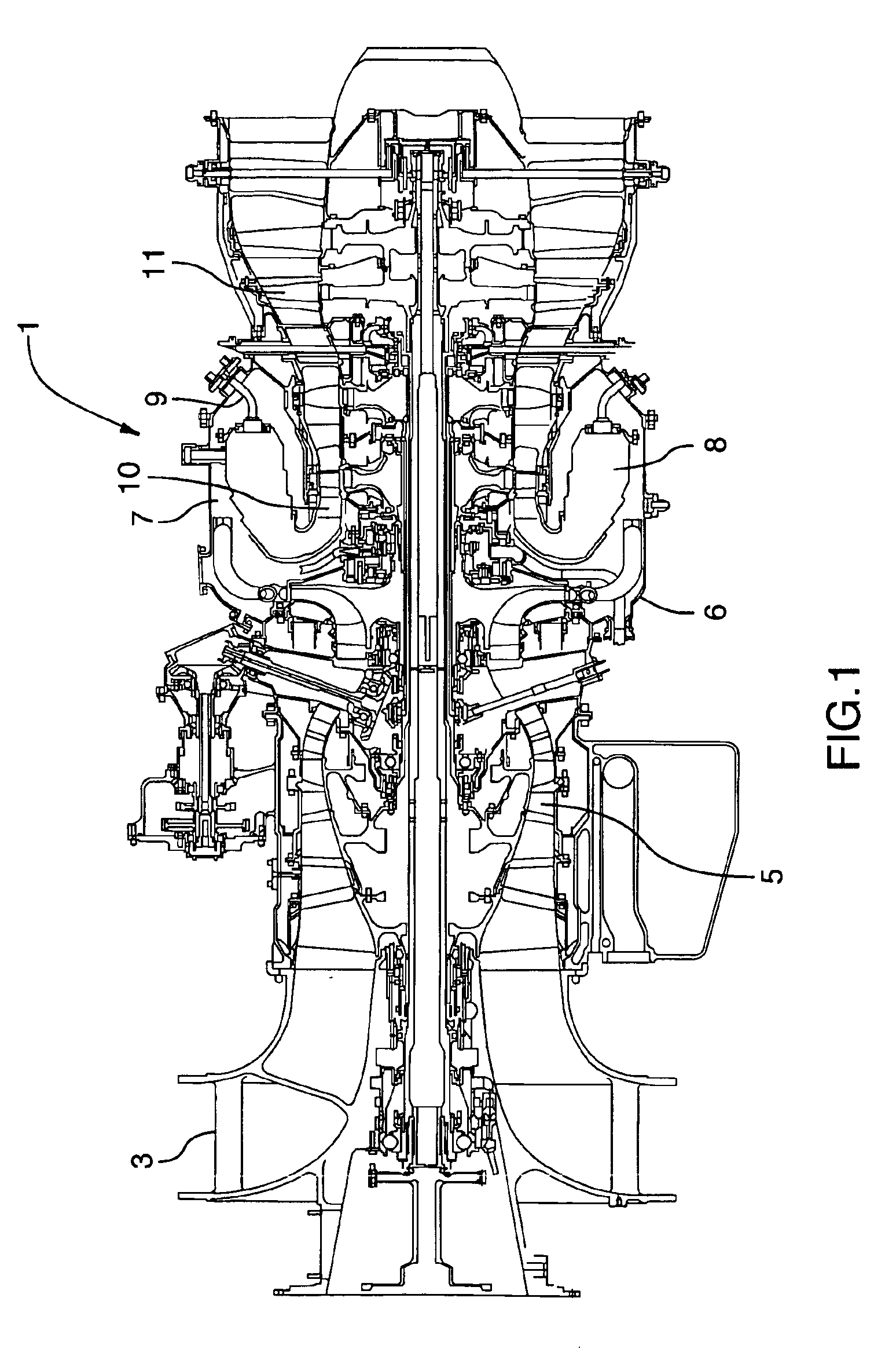
FIG. 1 shows an axial cross-section through a typical industrial gas turbine (IGT) engine. It will be understood that the invention may be applicable to almost any type of IGT engine with a combustor and fuel nozzles. Air intake into the engine 1 passes in an inlet 3 into a compressor portion 5, through a diffuser 6 and then into a plenum 7 that surrounds a combustor 8. Fuel is supplied to the combustor 8 through fuel nozzles 9, which also mixes fuel with air from the plenum 7 as it is injected into the combustor 8 as a fuel air mixture that is then ignited. A portion of the compressed air within the plenum 7 is admitted into the combustor 8 through orifices in the side walls to create a cooling air curtain along the combustor walls or is used for cooling to eventually mix with the hot gases from the combustor and pass over the nozzle guide vane 10 and turbines 11 before exiting the engine 1 as exhaust.

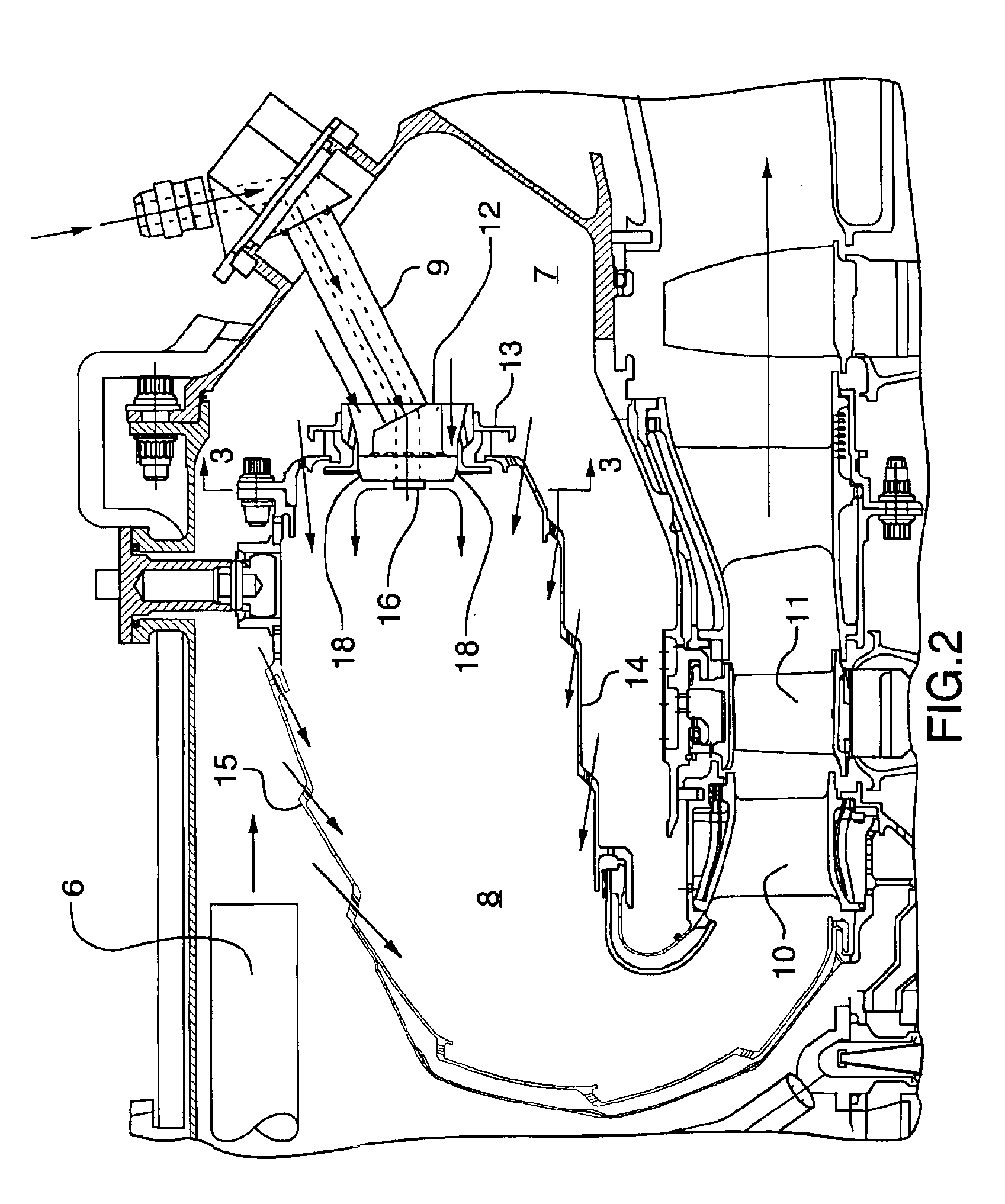
FIG. 2 shows an enlarged view of the reverse flow combustor 8 (though, of course ...


PUM


Abstract

A gas fuel nozzle for mounting in a combustor wall of a gas turbine engine, with an at least partially radially-directed array of gas fuel outlets extending beyond an air flow head having an array of compressed air jet apertures around the gas fuel outlets. The air flow head also has a deflector for creating an axial flow of air for deflecting in an axial direction the radially-injected gas fuel.

Description

TECHNICAL FIELDThe invention relates to a natural gas fuel nozzle for a gas turbine engine and, more particularly, a nozzle adapted to permit conversion from a liquid fuel nozzle configuration to a natural gas configuration on an aero derivative gas turbine engine with minimal change to the design of other components.BACKGROUND OF THE ARTThe technical field to which the invention relates is a gas turbine engine combustor with the flexibility of using liquid fuel or natural gas fuel nozzles interchangeably. Many combustors for industrial engines in the prior art include dual fuel nozzles that are mounted in combustor walls and can receive both liquid fuel and natural gas fuel at the same time for mixing with compressed air.The invention however is most advantageously applied to an aero derivative industrial gas turbine engine. Such engines are used for stationary industrial applications but incorporate the standard components from aircraft gas turbine engine designs for efficiency an...

Claims


Application Information

Patent Timeline
IPC IPC(8): F23R3/12F23R3/28F23R3/54F23R3/04F23R3/00
CPCF23R3/12F23R3/54F23R3/283Y02T50/675Y02T50/60
Inventor OSKOOEI, SAEIDMCCALDON, KIAN
Owner PRATT & WHITNEY CANADA CORP
Why Eureka
Try Eureka