Contact lens with transition

a contact lens and transition technology, applied in the field of bifocal contact lenses, can solve the problems of wearer discomfort, disturbing image jump, general poor tolerance, inadequate lens movement, etc., and achieve the effect of less visibl

Inactive Publication Date: 2005-03-29
SOFTFOCAL
View PDF28 Cites 49 Cited by
  • Summary
  • Abstract
  • Description
  • Claims
  • Application Information

AI Technical Summary

Benefits of technology

According to the present invention, monocentric bifocal contact lenses and intraocular lenses with upper and lower optical power zones are connected by a transition comprising a family of sigmoidal curves. The ends of the sigmoidal curves have common tangents with the curves of the adjacent power zones at their boundaries. Each sigmoidal curve begins with a common tangent at the boundary of the lower zone and climbs with increasing positive slope to an inflection point, whereupon it continues to climb with decreasing positive slope until reaching the upper zone curve, with which it has a common tangent. T

Problems solved by technology

U.S. Pat. Nos. 4,549,794 (Loshaek); 5,635,998 (Baugh); 4,618,229 (Jacobstein) Ezekiel, 2002, but generally these lenses have inadequate lens movement or produce discomfort to the wearer.
Unfortunately, an abrupt change in slope at the transition between two adjacent power zones is accompanied by a prismatic optical difference, which causes the wearer of the contact lens to observe a change in the image position when his gaze is shifted between the distance and near zones, a phenomenon known as image jump.
Most contact lens wearers find that image jump is disturbing and generally poorly tolerated.
Furthermore, if the lens assumes a position on the eye such that the transition lies in front of the pupil, the prismatic difference of light passing into the eye simultaneously from both the distance and near zones will cause the wearer to experience image doubling, which is intolerable to the lens wearer.
Unfortunately, the optical advantage of monocentricity is accompanied by a physical

Method used


Image

  • Contact lens with transition
  • Contact lens with transition
  • Contact lens with transition

Examples


Embodiment Construction

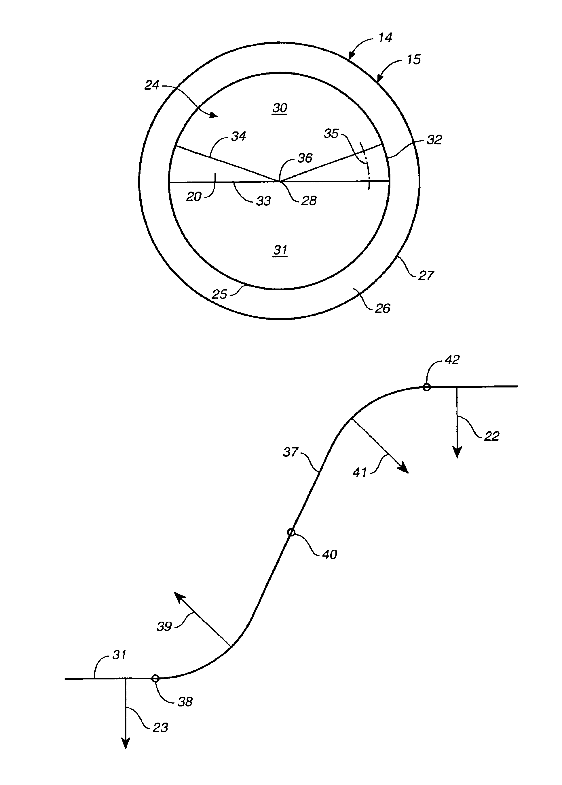
FIG. 6 is a plan view of a front surface 15 of a bifocal contact lens 14, in accordance with the invention. Front surface 15 is comprised of bifocal area 24 that is limited by bifocal perimeter 25, and surrounded by peripheral zone 26 that extends to edge perimeter 27. Bifocal area 24 is comprised of an upper zone 30 of an optical power for distance vision and a lower zone 31 of an optical power for near vision, which are connected by transition 20. Transition 20 is comprised of a midpoint 28, a periphery 32, a lower boundary 33 with lower zone 31 and an upper boundary 34 with upper zone 30. Lower boundary 33 follows a straight line in a horizontal orientation and upper boundary 34 follows two straight lines that are angled upward on each side from transition midpoint 28 to transition periphery 32.

A sigmoidal-curve path 35 is represented by an arc that is concentric with midpoint 28 of transition 20. Midpoint 28 of transition 20 coincides with a geometric center 36 of lens 14.

FIG. 7...


PUM


Abstract

A monocentric bifocal contact lens with upper and lower optical power zones is connected by a transition comprising a family of sigmoidal curves. The sigmoidal curve begins with a common tangent at the boundary of the near zone and, with a reversal of sign from the near zone curve, climbs with increasing positive slope to an inflection point, whereupon it continues to climb with decreasing positive slope until reaching the distance zone curve, with which it has a common tangent. There is no discontinuity in the first derivative of the curve throughout its length. A sigmoidal curve can be constructed from numerous mathematical functions, examples of which include polynomial, conic, transendental, or cumulative distribution curves.

Description

BACKGROUND OF THE INVENTION1. FieldThis invention relates to bifocal contact lenses and bifocal intraocular lenses with upper and lower optical power zones.2. Prior ArtBifocal contact lenses are lenses with at least two regions of different optical powers, known as zones or segments. Usually, one power is chosen to provide the wearer with clear distance vision and the second power to provide clear near vision, but any two powers may be selected. Bifocal contact lenses also may be called multifocal contact lenses, although the latter term is sometimes reserved for lenses comprised of at least three regions with different optical powers or regions of variable power, as in U.S. Pat. Nos. 5,517,260 (Glady) and 5,754,270 (Rehse.) Bifocal contact lenses have some features in common with bifocal intraocular lenses and some differences.Bifocal contact lenses generally are classified into two types, concentric and vertically segmented. Both types can be produced as rigid or soft contact lens...

Claims


Application Information

Patent Timeline
IPC IPC(8): G02C7/04
CPCG02C7/042G02C7/045G02C7/043G02C7/048
Inventor MANDELL, ROBERT B.CAMPBELL, CHARLES E.
Owner SOFTFOCAL
Why Eureka
Try Eureka