
Light module and flat panel display including the light module

a technology of light module and flat panel display, which is applied in the field of light module, can solve the problems of unstable brightness, low brightness of one face, and ineffective utilization of light source, and achieve the effect of simple structure and easy assembly

Inactive Publication Date: 2005-03-29
INNOLUX CORP
View PDF3 Cites 55 Cited by
  • Summary
  • Abstract
  • Description
  • Claims
  • Application Information

AI Technical Summary

Benefits of technology

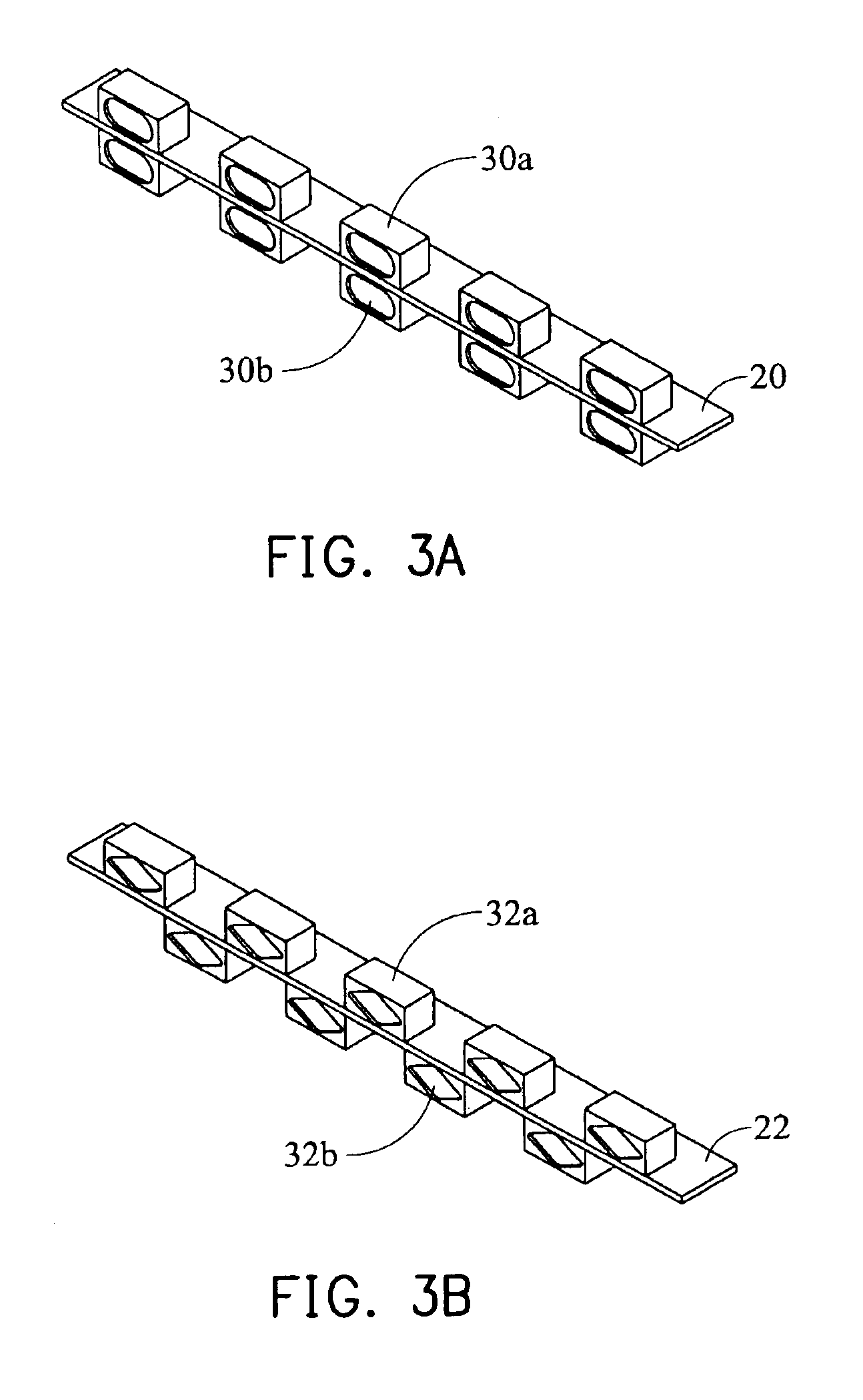
The present invention provides a light module with two sets of light sources on the same printed circuit board, which requires only one power supply and has a simple structure. The light module can be used in a dual-faced flat panel display, where the upper and lower light guiding plates can directly receive light. The quantities of light sources on the printed circuit board can be increased or decreased to adjust the brightness on the upper and lower faces. The technical effects of the invention include increased flexibility and efficiency in designing light modules for flat panel displays.

Problems solved by technology

Therefore, the light source cannot be effectively utilized.
The brightness (luminance) is unstable, that is, the brightness of one face is lower, and the brightness of the other face cannot achieve the best result.
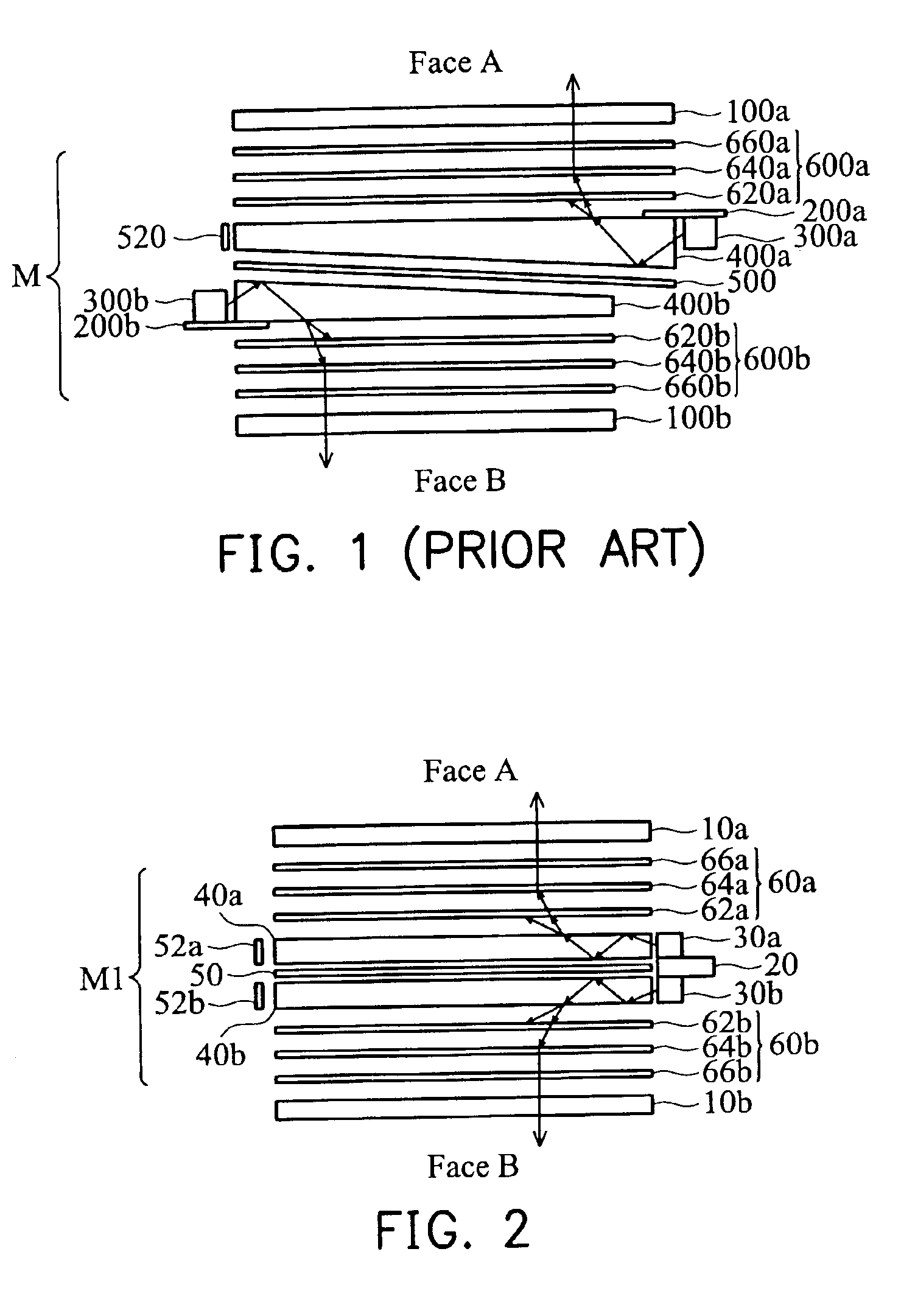
The above structure has the following disadvantages:(1) Face B has a much lower brightness than face A and it is difficult to control the stability standard of brightness.(2) The light source cannot be effectively utilized and the brightness of face A cannot achieve the best result.(3) The flat panel display with high brightness on both faces cannot be produced.(4) The size along the y-axis direction is larger.(5) Since the two light sources are disposed on two printed circuit boards respectively, two power supplies are needed.
Thus, the structure is complicated and is not easy to assemble.

Method used


Image

  • Light module and flat panel display including the light module
  • Light module and flat panel display including the light module
  • Light module and flat panel display including the light module

Examples


Embodiment Construction

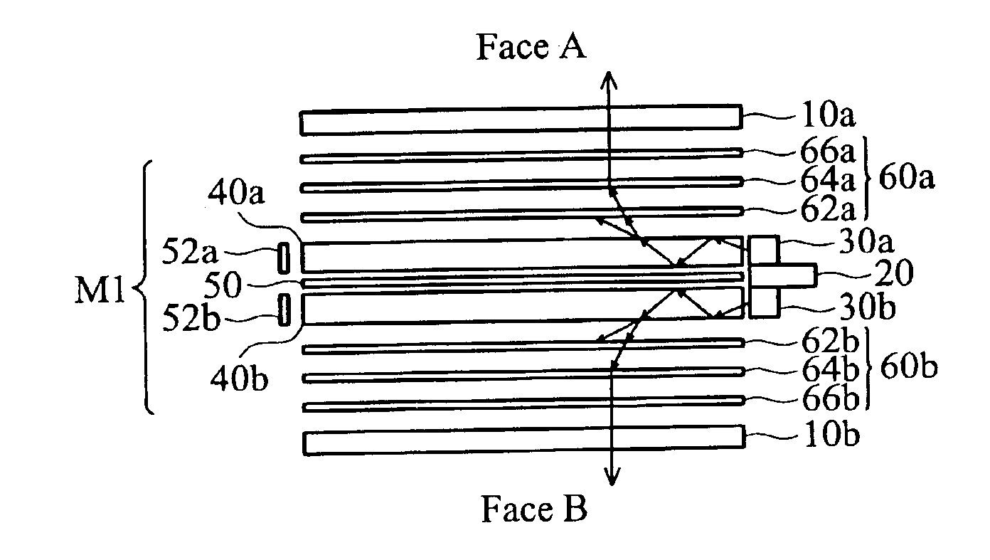
FIG. 2 is a cross-section of a flat panel display according to a first preferred embodiment of the present invention. The flat panel display of FIG. 2 is dual-faced and the two display panels are of approximately the same size. The flat panel display includes an upper display panel 10a, a lower display panel 10b and a light module M1 interposed between the two display panels. The display panel can be a liquid crystal display (LCD) panel. The light module M1 includes a printed circuit board 20, two sets of light sources 30a and 30b, two light guiding plates 40a and 40b, reflector sheets 50, 52a, and 52b, and two sets of optical sheets 60a and 60b.

Still referring to FIG. 2, the feature of the present invention is that only one printed circuit board 20 is used and the two sets of light sources 30a and 30b are respectively disposed on upper and lower surfaces of the printed circuit board 20. The light guiding plate 40a is disposed adjacent to the light source 30a. The light emitted fro...


PUM

PropertyMeasurementUnit
shapeaaaaaaaaaa
brightnessaaaaaaaaaa
luminanceaaaaaaaaaa

Abstract

A light module and a flat panel display including the light module. The light module includes a printed circuit board having a first surface and a second surface; a first light source disposed on the first surface of the printed circuit board; a second light source disposed on the second surface of the printed circuit board; and a light guiding plate disposed adjacent to the printed circuit board, for guiding light emitted from the first and / or the second light sources to a first surface of the light guiding plate.

Description

BACKGROUND OF THE INVENTION1. Field of the InventionThe present invention relates to a light module, and more particularly to a light module, in which light sources are provided on upper and lower surfaces of a single printed circuit board.2. Description of the Prior ArtIn recent years, dual face flat panel displays have developed quickly and have been applied in electronic products such as mobile phones. Generally, the conventional dual face flat panel display uses only one light source for two display panels. Therefore, the light source cannot be effectively utilized. The brightness (luminance) is unstable, that is, the brightness of one face is lower, and the brightness of the other face cannot achieve the best result.In order to improve the above disadvantage, some researchers use two light sources to supply two display panels. FIG. 1 is a cross-section of a conventional dual-faced LCD, which includes upper and lower LCD panels 100a and 100b, and a light module M interposed betw...

Claims


Application Information

Patent Timeline
Patent Type & Authority Patents(United States)
IPC IPC(8): F21V8/00G02F1/13357F21Y101/02
CPCG02B6/0046G02B6/005G02B6/0068H05K1/181H05K2203/1572H05K2201/09709H05K2201/10106Y02P70/50
Inventor CHUANG, MENG JU
Owner INNOLUX CORP
Learn More