Handle connector

a technology of handle and connector, which is applied in the direction of couplings, rod connections, manufacturing tools, etc., can solve the problems of limited number, difficult to keep these connections from loosening during use, and the handle coming loose from the head, etc., and achieves the effect of convenient insertion, simple manufacturing, and easy fabricated

Inactive Publication Date: 2005-03-29
QUICKIE MFG
View PDF22 Cites 8 Cited by
  • Summary
  • Abstract
  • Description
  • Claims
  • Application Information

AI Technical Summary

Benefits of technology

It is a further object of the present invention to provide a handle connector which easily receives and maintains a handle securely to the head.
It is still another object of the present invention to provide a handle connector which employs a floating web section, which, with the application of appropriate compressive force, ensures a tight fit between handle and connector—to maintain the integrity of the joint between these elements.
It is still a further object of the present invention to provide a handle connector which is easily fabricated and simply and efficiently installed between handle and head.
It is another object of the present invention to provide a handle connector which allows a direct and tight handle to head connection, especially for non-tapered handles.
These and other objects of the invention are accomplished by the handle connector of the present invention which is formed as a unitary integral body, preferably of die-cast construction. The connector has two distal ends. At one end, there is an opening for receiving a handle. The other end of the connector extends outwardly and is configured to mate with the head of a broom, mop, or similar manual tool. The body of the connector includes a floating web comprising a substantially flat section and laterally flanking slots. A bolt and wing nut are provided for joining the handle to the connector. As the wing nut is manually tightened against the connector, it applies a compressive force against the flat section of web, which flexes inward in relation to the handle, ultimately contacting the outside surface of the handle. Continued manual tightening ensures for a tight fit between handle and connector and rigidly secures the joint between these tool components.

Problems solved by technology

There have been numerous means employed to accomplish this seemingly simple objective; however, only a very limited number of connection systems have succeeded in accomplishing an integral, permanently tight fit between handle and head—especially during prolonged use of the tool.
Such a sleeve, however, often cracks or breaks—resulting in the handle coming loose from the head.
It is difficult to keep these connections from loosening during use.
However, it is generally difficult to permanently and rigidly secure a handle, especially a non-tapered one, with this type of connector.
There is insufficient connector-to-handle contact, which results in movement of the handle within the connector.
The common practice of merely joining a handle to a connector by screws or other means, usually results in a less than secure connection.
Typically the connection is loose or becomes loose during use, again resulting in annoying movement between connector and handle.

Method used


Image

  • Handle connector
  • Handle connector
  • Handle connector

Examples


Embodiment Construction

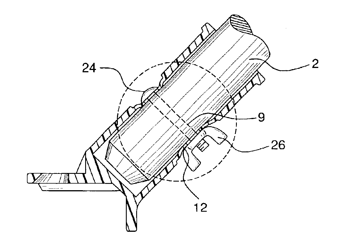
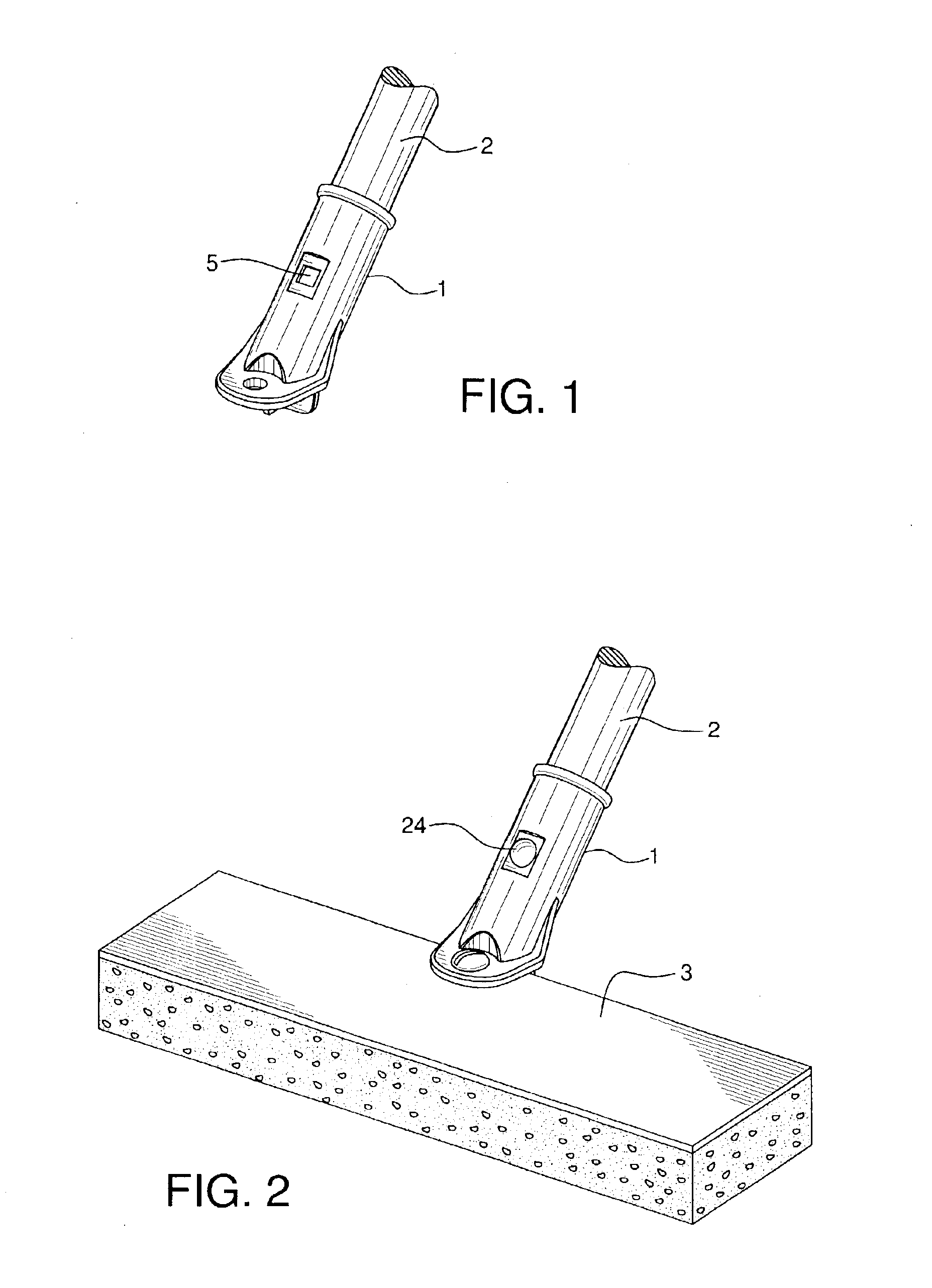
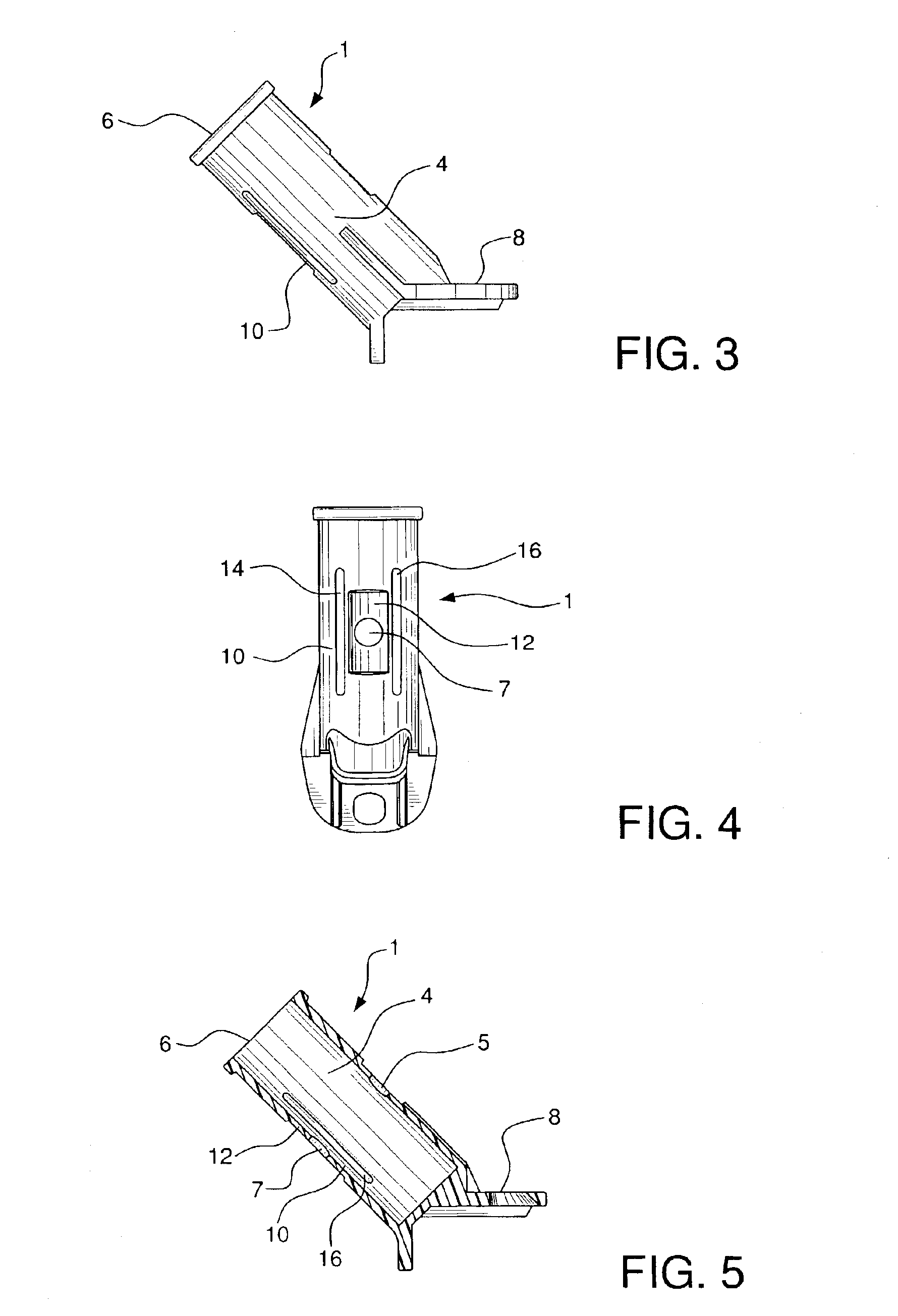
Connector 1 is formed as an integral, unitary body, optimally of die-cast construction. It is substantially cylindrical in configuration to accept handle 2. Connector 1 has a central section 4 and distal ends 6 and 8. End 6 is open to receive the end of handle 2. The other end 8 of connector 1 comprises an extension which extends outwardly and is configured to mate with head 3 of a broom, mop, or other manual tool. Openings 5 and 7 are configured to receive an attachment device, such as bolt 24, for securing handle 2 via connector 1 to head 3.

Connector 1 further comprises, at central section 4, floating web section 10 which includes substantially flat section 12 on the outer surface of the connector, slots 14 and 16 which laterally flank section 12, and opening 5. Opening 5 is in alignment with opening 7 and is located on the front, outer surface of connector 1, opposite flat section 12. Web section 10 is formed so as to allow flexure of connector 1 at flat section 12, when a compre...


PUM


Abstract

A handle connector for securing the head of a cleaning tool to its handle is formed as a unitary integral body, preferably of die-cast construction. The connector has two distal ends. At one end, there is an opening for receiving a handle. The other end of the connector extends outwardly and is configured to mate with the head of a broom, mop, or similar manual tool. The body of the connector includes a floating web comprising a substantially flat section and laterally flanking slots. A bolt and wing nut are provided for joining the handle to the connector. As the wing nut is manually tightened against the connector, it applies a compressive force against the flat section of web, which flexes inward in relation to the handle, ultimately contacting the outside surface of the handle. Continued manual tightening ensures for a tight fit between handle and connector and rigidly secures the joint between these tool components.

Description

BACKGROUND OF THE INVENTIONThis invention relates to the connection of a handle to the head of a broom, mop, or other similar manually operated tool. There have been numerous means employed to accomplish this seemingly simple objective; however, only a very limited number of connection systems have succeeded in accomplishing an integral, permanently tight fit between handle and head—especially during prolonged use of the tool.For instance, handles with tapered ends often use tapered sleeves into which the tapered ends are fitted. The sleeve is then inserted into an opening in the head and secured to the head. Such a sleeve, however, often cracks or breaks—resulting in the handle coming loose from the head. Some handles with non-tapered ends have threaded connections which threadingly mate with their heads. It is difficult to keep these connections from loosening during use. In such cases, an extra component, such as a locking bracket, is used to maintain the handle in position. Anot...

Claims


Application Information

Patent Timeline
Patent Type & Authority Patents(United States)
IPC IPC(8): B25G3/26B25G3/00
CPCB25G3/26Y10T403/7079Y10T403/7084Y10T403/46
Inventor PETNER, ROBERT E.
Owner QUICKIE MFG
Why Eureka
Try Eureka