Variable geometry diffuser mechanism

Inactive Publication Date: 2005-03-29
JOHNSON CONTROLS TYCO IP HLDG LLP
View PDF24 Cites 89 Cited by
  • Summary
  • Abstract
  • Description
  • Claims
  • Application Information

AI Technical Summary

Benefits of technology

An advantage of the present invention is that the rotational motion of the drive ring can be converted to axial motion by the mechanism of the present invention. This axial motion can be achieved rapidly and effectively in response to appropriate signals from the controller by an axially movable actuating rod.
Another advantage of the present invention is that the diffuser ring of the present invention can be placed anywhere within the compressor as long as it can be extended into and retracted from the diffuser gap. Because the support blocks carry the load of the diffuser ring, the diffuser ring can assume any position, provided of course, that it can be extended or retracted into the diffuser gap. Thus, unlike prior art devices, the diffuser ring may be placed further downstream in the diffuser, if desired. Since the diffuser ring does not have to be carefully match machined to mate with structures such as the inner diameter of the nozzle base plate and is not supported on the casing, and requires only the extension or

Problems solved by technology

However, when the flow of fluid through the compressor is decreased, and the same pressure differential is maintained across the impeller, the fluid flow through the compressor often becomes unsteady.
These stalled pockets of fluid are problematic in that they create noise, cause vibration, and reduce the efficiency of the compressor.
If the fluid flow is further decreased, the fluid flow will become even more unstable, in many cases causing a complete reversal of fluid flow.
In addition to creating noise, causing vibration, and lowering compressor efficiency, fluid surge also creates pressure spikes and can damage the compressor.
Displacing this fluid so the ring can be

Method used


Image

  • Variable geometry diffuser mechanism
  • Variable geometry diffuser mechanism
  • Variable geometry diffuser mechanism

Examples


Example

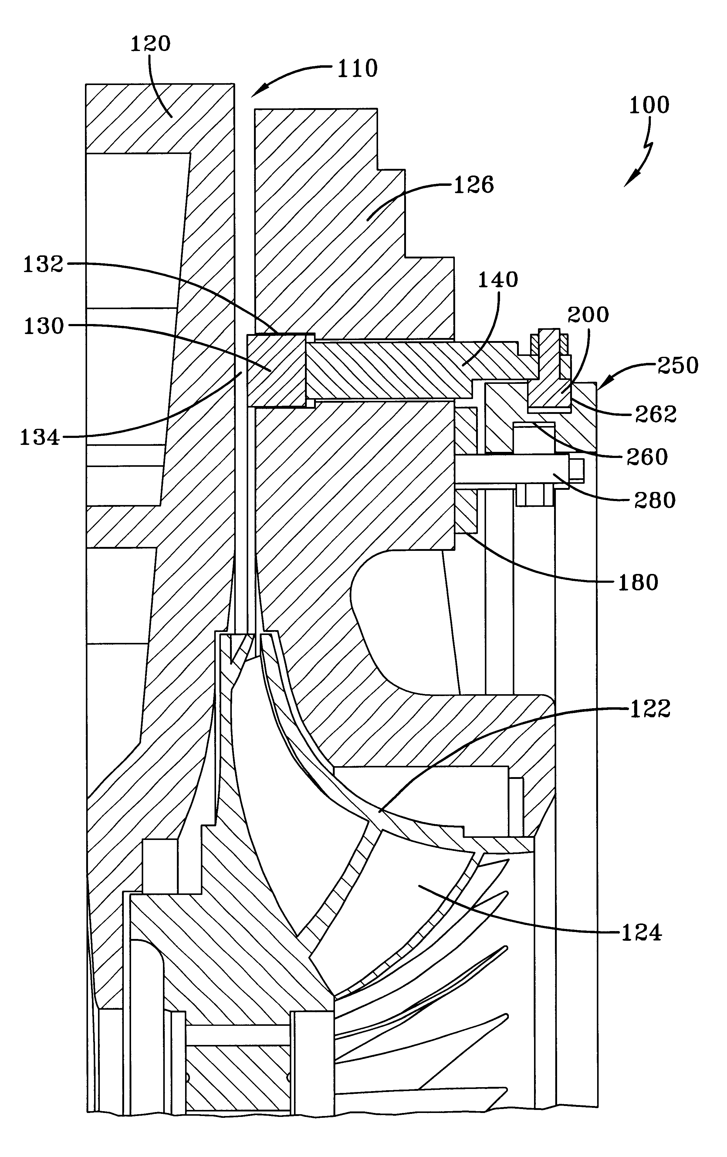
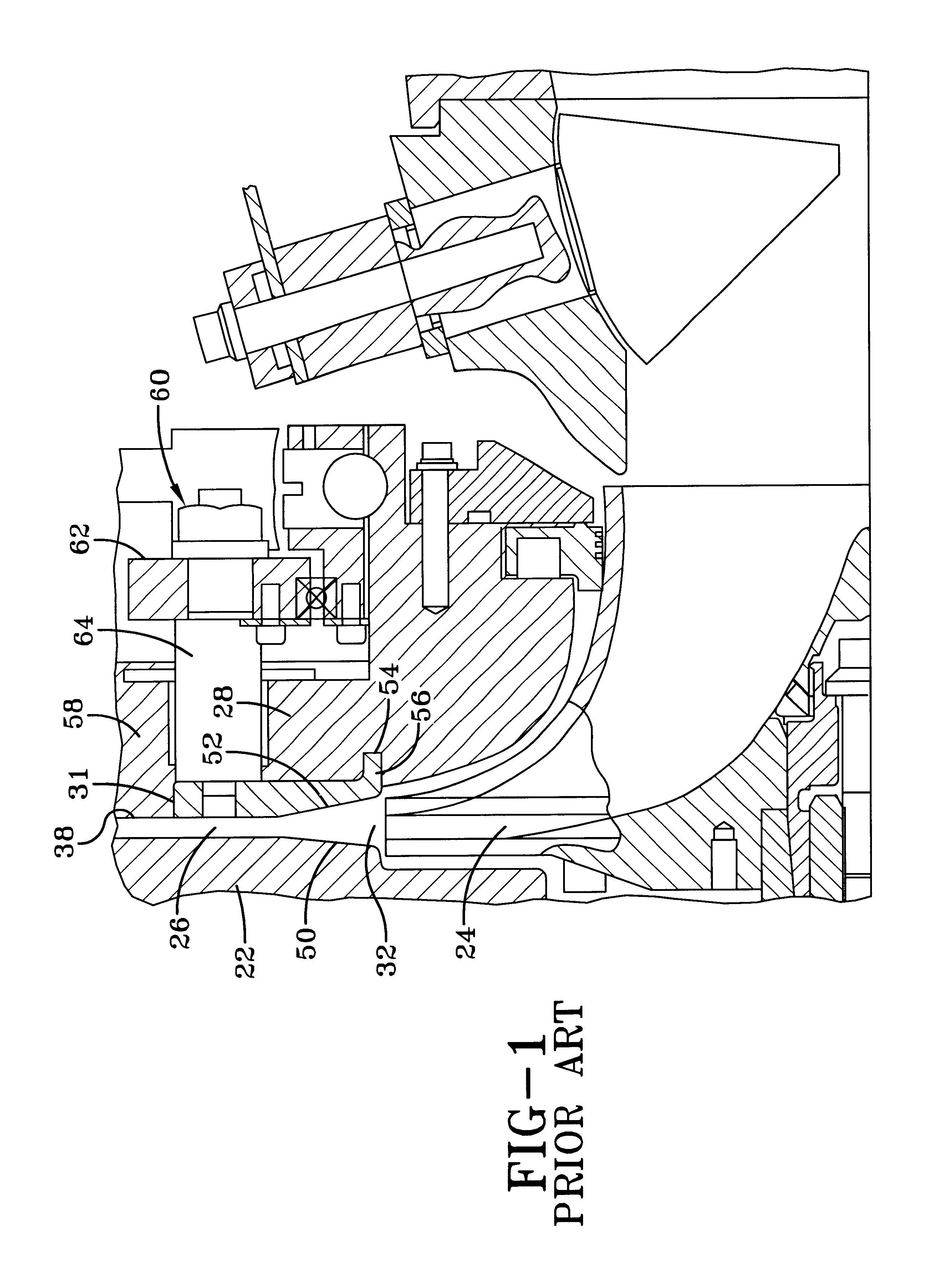
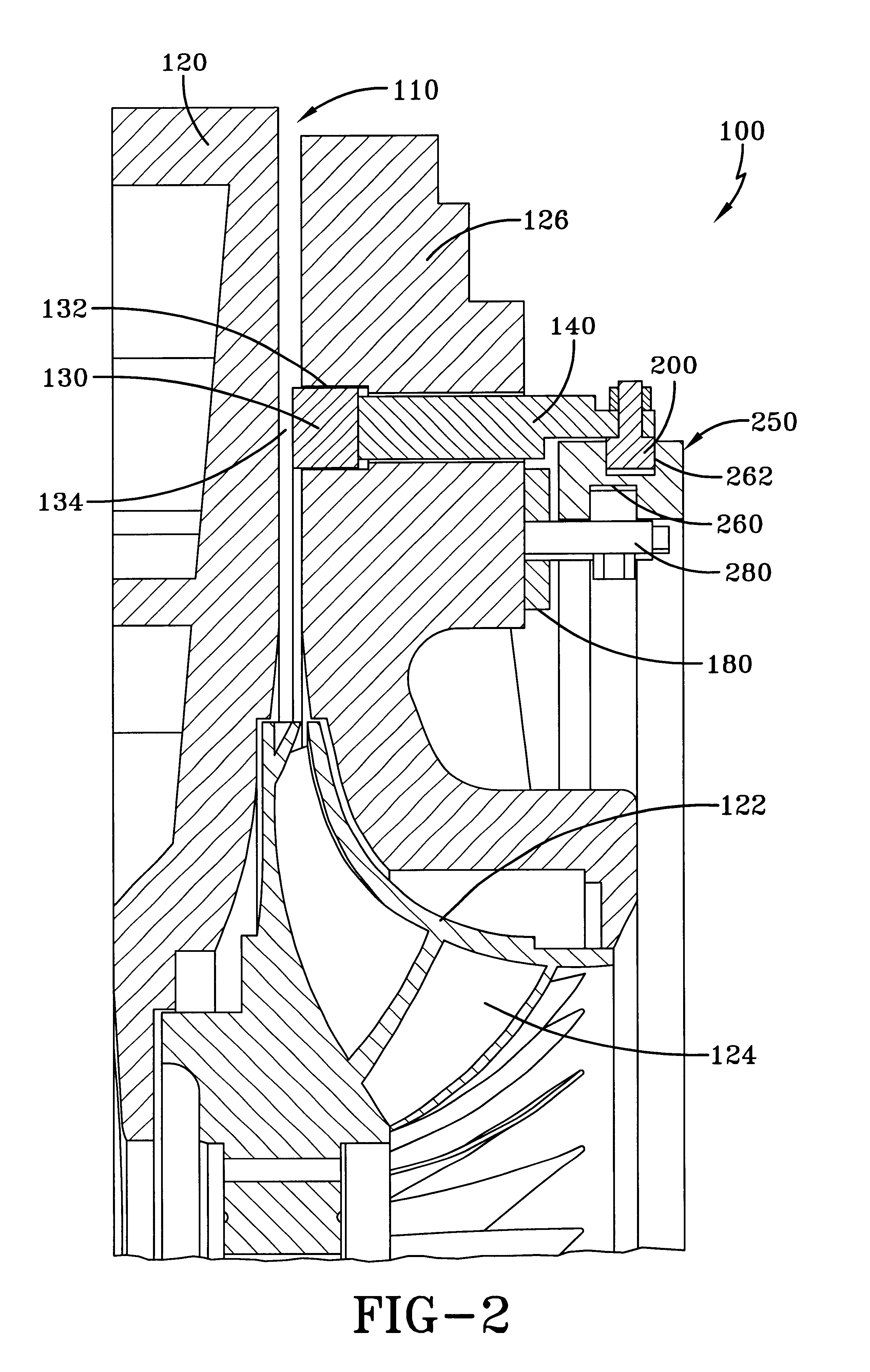
The present invention is a variable geometry diffuser mechanism for a centrifugal compressor. FIG. 1 depicts a prior art variable capacity centrifugal compressor having a different diffuser configuration. The system of the prior art utilizes a movable wall as an annular ring positioned adjacent to the exit of the impeller. The wall is movable into the diffuser space, as is typical, to control the flow of fluid through the diffuser. The annular ring is disposed on the base plate. The ring is connected to an intricate support structure for moving the wall that includes an annular push ring and pins connected to the wall. A drive ring is mounted on the base plate via a ball bearing arrangement. The drive ring pushes annular push ring which in turn moves the wall. The ball bearing arrangement rides in a race in the drive ring and in inclined races in the base plate. The rotational motion of the drive ring by any suitable mechanism thus results in an axial movement of the moveable wall i...


PUM


Abstract

A system for preventing stall in a centrifugal compressor. The compressor includes an impeller rotatably mounted in a housing and a nozzle base plate fixed to the housing adjacent the impeller. The nozzle base plate cooperates with the housing to define a diffuser gap. The base plate includes a plurality of mechanism support blocks positioned on the backside of the nozzle base plate. A drive ring, mounted to the support blocks, is rotationally moveable with respect to the support blocks and the nozzle base plate between a first position and a second position. Connected to the drive ring is a diffuser ring that moves in response to movement of the drive ring. Diffuser ring moves between a retracted position that is not within the diffuser gap and an extended position extending into the diffuser gap to constrict the gap opening and reduce the flow of fluid through the diffuser gap. The diffuser ring can be positioned at any location between the retracted and extended position to control the amount of fluid flowing through the diffuser gap.

Description

FIELD OF THE INVENTIONThe present invention is directed to centrifugal compressors, and more particularly to a system for controlling the flow in the diffuser of a variable capacity turbo compressor.BACKGROUND OF THE INVENTIONCentrifugal compressors are useful in a variety of devices that require a fluid to be compressed. The devices include, for example, turbines, pumps, and chillers. The compressors operate by passing the fluid over a rotating impeller. The impeller works on the fluid to increase the pressure of the fluid. Because the operation of the impeller creates an adverse pressure gradient in the flow, many compressor designs include a diffuser positioned at the impeller exit to stabilize the fluid flow.It is often desirable to vary the amount of fluid flowing through the compressor or the pressure differential created by the compressor. However, when the flow of fluid through the compressor is decreased, and the same pressure differential is maintained across the impeller,...

Claims


Application Information

Patent Timeline
IPC IPC(8): F04D27/02F04D29/46
CPCF04D29/464F04D27/0253F05D2250/52F04D17/08F04D29/002F04D29/056F05D2210/12F16B5/02Y10S415/00Y10S417/00
Inventor NENSTIEL, KURT
Owner JOHNSON CONTROLS TYCO IP HLDG LLP
Why Eureka
Try Eureka